Forney Corporation
UNIFLAME User’s Manual
Publication 372000-48 Rev H
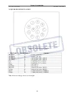
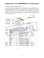
3.3 WIRING HARNESS ASSEMBLY LAYOUT
To provide a service point at the burner front or an easy method to wire the UNIFLAME Series flame
detectors in a “multi-drop” configuration for remote communications, Forney offers a wiring harness in
four different lengths (10, 15, 20, 30 Ft.). The harness has a pre-wired female quick disconnect to plug
into the male quick disconnect on the detector. The other end of the wiring harness has a NEMA 4
conduit box with a 16 point terminal strip. Twelve (12) wires are pre-wired to the female quick
disconnect. The remaining four (4) terminals are used to “daisy-chain” the remote communication wires
from one detector to another.
Figure 10 – Wiring Harness Assembly Layout
Cable Wire
Color Terminal
Function
Termination
Black/Red
1
Power (+) 24 Vdc
White/Blue
2
Power (-) 24 Vdc
Detector
White/Black
3
Flame Relay (N.O. contacts)
Back to
Cable
White/Red
4
Flame Relay (N.O. contacts)
the Control
Red
5
Fault Relay (N.C. contacts)
Room
Pink
6
Fault Relay (N.C. contacts)
(To BMS)
Violet
7
4-20 mA (+)
Grey/Red
8
4-20 mA (-)
Blue/Red
9
Remote File Select 1 (RFS1)
Yellow
10
Remote File Select 2 (RFS2)
Brown
11
Communications A (COMM A)
Orange
12
Communications B (COMM B)
Belden
Black
11
Communications A (COMM A)
To next
Cable
Clear
12
Communications B (COMM B)
Detector
Belden
Black
11
Communications A (COMM A)
To next
Cable
Clear
12
Communications B (COMM B)
Detector
11


