12"
9"
48"
18"
CENTRAL
FURNACE
6" CHIMNEY
18"
18"
6" SOLID DAMPER
6" BAROMETRIC
DRAFT REGULATOR
(OPTIONAL)
NON-COMBUSTIBLE FLOOR
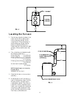
The furnace should be located in the
same room as the central system
and as close as possible, but no
closer than 9". There should be no
wall between the furnace and the
warm air outlet duct that is con-
nected directly to the warm air outlet
plenum of the central furnace. See
Fig. 2.
The unit will require installation with
the following clearances:
Unit to sidewall . . . . . .12" (305 mm)
Unit to backwall . . . . . 30" (760 mm)
Chimney connector pipe to sidewall
. . . . . . . . . . . . . . . . . . 21" (530 mm)
Chimney connector pipe to backwall
. . . . . . . . . . . . . . . . . . 18" (460 mm)
Hot air ducts to combustibles
. . . . . . . . . . . . . . . . . . . 6" (150 mm)
NOTE: Install only on a noncom-
bustible floor.
(REFER TO FIG. 2 & 3)
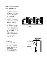
Place the furnace on a noncombus-
tible floor.
Check figures 2 and 3. Be sure you
have the clearances shown from the
furnace and the connector pipe to
combustible surfaces. If you have a
solid brick or stone wall behind your
heater, you can place the furnace as
close as you wish to the wall. If the
wall is only faced with brick or stone,
treat it as a combustible wall.
1.
2.
3.
4.
Locating the Furnace
7
FIG. 3
FIG. 2
Содержание Clayton 1537Q
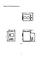
Страница 6: ...24 1 16 40 11 16 32 1 4 3 1 2 9 33 7 8 43 7 8 Model 1537Q Dimensions FIG 1 6 ...
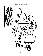
Страница 22: ...Model 1537Q Parts 22 ...
Страница 31: ...31 Notes ...


