background image

DS1054-066B

P10

3.   How to set the pushbutton as centralised

     1.   Press the transmitter pushbutton 

10

times (Configuration Menu). The transmitter LED will flash rapidly.

     2.   Press the chosen pushbutton 

6

times while the LED is flashing.

     3.   At the end of the press sequence, the LED will flash 

6

times to confirm the configuration

4.   How to set centralisation to operate: lights (default), window shutters or “lights and window shutters”

     By  default  the  central  button  of  the  transmitters  ABE2BPP  is  set  to  operate  the  lighting  modules  (MTR1300EBRP,

MTR2000ERP and MTV500ERP).

     Follow the step described below if device 5454815 is used and you want to operate the shutters as well as the lights.

Otherwise go directly to point 5. When using device 5454816, the centralisation must be defined so that the centralised

control either drives the MVR500EBRP and MVR500ERP shutter modules or drives both lights and shutters at the same

time. 

Proceed as follows:

     1.   Press any pushbutton on the transmitter 

10

times (Configuration Menu). The transmitter LED will flash rapidly.

     2.   While the LED is blinking, press the chosen button 

11

times to control the shutters only or 

20

times to control the shutters

and the lights.

     3.   At the end of the press sequence, the LED will blink 

once

if shutter centralisation was selected or 

10

times if both shutter

and light centralisation has been selected.

5.   How to define pushbutton operating mode

Follow the instructions in the next paragraph to establish the effect of the centralised pushbutton on the lights or window shutter

modules.

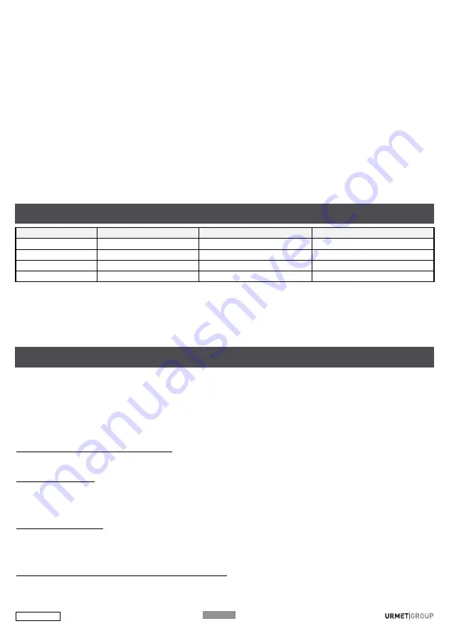
OPERATING MODE MTR1300EBRP / MTR2000ERP MTV150EBRP / MTV500ERP MVR500EBRP / MVR500ERP

Operating mode  1*

On / Off

Dim / Off

Up / Stop / Down

Operating mode  

2

Not used

Recall Memory Level

Intermediate position

Operating mode  

3

On

On

Up / Stop

Operating mode  

4

Off

Off

Down / Stop

* Default configuration

To change the operating mode of a pushbutton:

1. Press any pushbutton on the transmitter 

10

times (Configuration Menu).

    The transmitter LED will flash rapidly.

2. While the LED is flashing, press the chosen button from 

1

to 

4

times to select the required operating function.

3. The LED will flash from 

1

to 

4

times to confirm configuration.

How to copy a pushbutton onto another pushbutton (between two different transmitters or on the same transmitter).

Copy all the connections configured on the button and also its configuration.
Important: 

The functions associated with a Yokis Hub (controlling a scenario, group controls) are not copied. Duplicate the

remote control using the YOKIS PRO or YnO App to make a copy.

1- Press the new button to be created

5

times. The LED will start flashing.

2- While the LED is blinking, hold the original button pressed (for 3 seconds) until the LED blinks.

3- Press the button to be created again until the LED blinks. The new button will now contain the programming sent.

How to duplicate the transmitter completely

This function can be used to copy all the buttons of the transmitter and their configurations.

Scenario and group control functions are maintained.

On the new transmitter:

1- Press any pushbutton on the transmitter 

10

times (Configuration Menu).

The transmitter LED will flash rapidly.

2- Press one of the pushbuttons 

14 

times while the LED is flashing.

3- The LED will flash at the end of the 

14

presses.

On the source transmitter:

1- Press any pushbutton on the transmitter 

10

times (Configuration Menu).

The transmitter LED will flash rapidly.

2- Press one of the pushbuttons 

14

times while the LED is flashing.

3- The LED will flash at the end of the 

14

press sequence.

How to restore default settings of a transmitter pushbutton

Default setting = clear button connections, go back to mode 1 (toggle), go back to direct mode.

1- Press any pushbutton on the transmitter 

10

times (Configuration Menu).

The transmitter LED will flash rapidly.

PUSHBUTTON OPERATING MODE

USEFUL FUNCTIONS

Содержание 5454815

Страница 1: ...e 5 impulsions rapides sur le BP du canal de l metteur E associer La LED de l metteur se met alors clignoter rapidement pendant 30 secondes indiquant ainsi l attente d une connexion Pendant que la LED...

Страница 2: ...de l metteur 3 A la fin des 14 impulsions la LED clignote La LED des 2 metteurs s arr te alors de clignoter Retour aux r glages d usine d un canal d un metteur R glage usine effacement des connexions...

Страница 3: ...un ordre de clignotement p riode de 0 5 secondes pendant 30 secondes La version de l metteur est inscrite au dos de celui ci Pour modifier la fonction de la touche suivre la proc dure suivante 1 Fair...

Страница 4: ...ui la trasmissione radio sia andata a buon fine In caso di portata insufficiente l aggiunta di un ricevitore intermedio consente di risolvere il problema cfr Aumento della portata IT DS1054 066B P4 MO...

Страница 5: ...etto funzionamento del bus radio YOKIS richiede che i moduli ricevitori siano tutti collegati sulla stessa fase L di alimentazione e non ci siano inversioni di fase L e neutro N su nessun modulo ricev...

Страница 6: ...nzionalit di un pulsante 1 Fare 10 pressioni rapide su di un pulsante qualunque del trasmettitore Menu Configurazione Il LED del trasmettitore lampegger velocemente 2 Mentre il LED lampeggia fare da 1...

Страница 7: ...solo con MAU500ER 16 Apertura temporizzata Per ottenere maggiori informazioni sulla creazione e configurazione del Bus Radio sui trasmettitori ed i ricevitori radio YOKIS leggere il codice QR qui a f...

Страница 8: ...ly if radio transmission was successful Adding an intermediate receiver will allow to solve a problem of insufficient range see How to increase the range DS1054 066B P8 DIRECT MODE Press the pushbutto...

Страница 9: ...mes the same one programmed in the previous step The transmitter LED will start flashing rapidly Press the Connect button once on the receiver R the transmitter and receiver LED will stop blinking DS1...

Страница 10: ...configuration To change the operating mode of a pushbutton 1 Press any pushbutton on the transmitter 10 times Configuration Menu The transmitter LED will flash rapidly 2 While the LED is flashing pres...

Страница 11: ...n or of the entire transmitter 14 Completely duplicate the transmitter 15 Restore default settings of a channel 24 Reset access points delete all radio bus access points 25 Restore transmitter default...

Страница 12: ...ionamiento de 10 a 50 C Protecci n IP30 Humedad relativa m x 80 Banda de radiofrecuencia 2400 2480 MHz Potencia m xima radio transmitida 10mW Transmisi n Bidireccional Tama o de los pulsadores A x A 2...

Страница 13: ...misor E el mismo que se program en el punto anterior el LED del emisor comienza a parpadear r pidamente Presionar 1 vez la palabra connect del receptor R el LED del transmisor y el receptor deja de pa...

Страница 14: ...ra modificar la funci n de un pulsador 1 Realizar 10 pulsaciones r pidas en un pulsador cualquiera del emisor Men Configuraci n El LED del emisor parpadea r pidamente 2 Mientras el LED parpadea realiz...

Страница 15: ...lecimiento de la configuraci n de f brica de un canale 24 Restablecimiento de los puntos de acceso Cancela todos los puntos de acceso al Bus Radio 25 Restablecimiento de la configuraci n de f brica de...

Страница 16: ...Funk bertragung zustande kommt Bei unzureichender Reichweite erm glicht das Hinzuf gen eines Zwischenempf ngers das L sen des Problems siehe Kap Erh hen der Reichweite DS1054 066B P16 DIREKTMODUS Auf...

Страница 17: ...r cken w hrend die Sender LED blinkt 3 Richten Sie einen Zugangspunkt auf dem Empf nger ein der sich am n chsten am Sender befindet indem Sie 7 Mal auf die Taste des Senders dr cken E derselbe der ber...

Страница 18: ...00ERP MVR500EBRP MVR500ERP Funktionsweise 1 Ein Ausschalten nderung Ausschalten Hochfahren Stopp Herunterfahren Funktionsweise 2 Nicht verwendet Speicher Einschalten Zwischenposition Funktionsweise 3...

Страница 19: ...V5 oder h here Versionen Kopie oder L schen der Verbindungen eines Tasters oder des gesamten Senders 14 Vollst ndiges Duplizieren des Senders 15 Wiederherstellung der werkseitigen Konfiguration eines...

Страница 20: ...eid 80 Radiofrekvensb nd 2400 2480 MHz Maksimal radioeffekt transmitteret 10mW Zendeigenschappen In twee richtingen Afmetingen toetsen L x A 22 5 x 45 mm Afmetingen module L x A x P 22 5 x 50 x 46 8 m...

Страница 21: ...r in te drukken E Terwijl het lampje van de zender knippert Druk op het woord connect op de ontvanger R terwijl het zenderled knippert 3 Maak een toegangspunt op de ontvanger die het dichtst bij de ze...

Страница 22: ...500ERP Werking 1 Inschakelen Uitschakelen Variatie Uitschakelen Stijging Stop Daling Werking 2 Niet gebruikt Geheugen inschakeling Tussenstand Werking 3 Inschakelen Inschakelen Stijging Stop Werking 4...

Страница 23: ...luiken V5 of hoger Kopie of verwijdering van de verbindingen van een knop of van de hele zender 14 De volledige zender kopi ren 15 De default instellingen van kanaal herstellen 24 De toegangspunten he...

Страница 24: ...ekniske specifikationer Netsp nding 230V 10 15 50Hz Modulets forbrug 0 3VA 0 1W Max 4 modtagere pr sender kanal Operating temperature from 10 to 50 C IP30 Max Luftfugtighed 80 Radiofrekvensb nd 2400 2...

Страница 25: ...ns lysdiode blinker 3 Opret den modtager der skal v re repeater som er n rmest senderen ved at trykke 7 gange p senderen E knap pen det samme som programmeret i det foreg ende trin Senderens LED vil b...

Страница 26: ...r DS1054 066B P26 Konfigurations mode MTR2000ERP MTV150EBRP MTV500ERP MVR500ER Konfigurations mode 1 T nd Sluk T nd Sluk Up Stop down Konfigurations mode 2 Ikke brugt Sidste indstilling Sidste eller m...

Страница 27: ...tomatiseringer senso rer etc Produkter styres af Radio Bus 10 Belysning standardkonfiguration 11 Vindue markiser mm 20 Belysning og Vindue markiser mm V5 eller mere Kopi r eller fjern forbindelserne m...

Страница 28: ...ie Tastenabdeckung des Moduls kann unter Beachtung des folgenden Vorgangs ersetzt werden De toetsbedekking van de module kan met de volgende procedure worden vervangen Det er muligt at udskifte module...

Страница 29: ...que el tipo de equipo radioel ctrico ABE2BPP ON OFF c digo art 5454815 y ABE2BPP UP DOWN c digo art 5454816 es conforme con la Directiva 2014 53 UE El texto completo de la declaraci n UE de conformid...

Страница 30: ...r nicos RAEE El s mbolo del contenedor de basura tachado con un aspa en el producto o en su embalaje indica que dicho producto no debe desecharse junto con los otros residuos dom sticos Por el contrar...

Отзывы: