


4G PRIMARY CELLULAR
ALARM COMMUNICATOR
®
4530EX
15
16
INSTALLATION (cont.)
D. Locating and Installing the 4530EX
The 4530EX is housed in a plastic enclosure. The installer needs to supply DC
power from the panel via the AUX output, or battery, via a separate DC power
source. Input DC current is listed on page 25.
After carefully considering all of the issues outlined in Installations - General
Considerations, page 12, proceed as follows:
1. Separate the top and bottom of the enclosure by depressing the tab on
the bottom of the unit and then tilting the bottom of the plastic top
outward and up.
2. Connect the antenna that is supplied with the 4530EX. The Antenna
supplied may differ from the ones depicted in the figures in this manual.
3. Go to the red, 4-position Dipswitch as shown in Figure 1 and set the
dipswitch as appropriate for this installation. (See DIP Switch Settings,
page 12.)
4. Place Dipswitch #4 (S4) in the ON position. The LEDs are now operating
in RSSI Mode. Locate a good mounting position based on a good
Received Signal Strength Indication (RSSI).
It is recommended that the
installation location demonstrate an RSSI of at least -80 dBm (two solid green
LEDs).
The minimum acceptable RSSI is -90 dBm (1 solid green LED).
5. Position the bottom of the 4530EX enclosure where it will be installed.
Use four (4) #6 screws and mount the unit using the four holes in the
enclosure’s plastic bottom.
6. Make sure that the unit’s antenna is connected.
7. Connect the positive (+) and negative (-) terminals of the 12V DC power
supply to terminals DC+ and DC - respectively on the 4530EX.
8. Double check to make sure that the RSSI is still showing a good signal
strength level.
9. Before connecting the alarm panel and the 4530EX, first:
a. Return Dipswitch #4 (S4) to the OFF position.
b. Disconnect the Positive and Negative connections to the
DC power source.
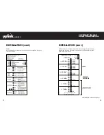
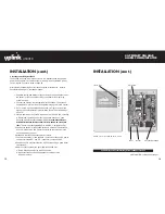
INSTALLATION (cont.)
FIGURE 1: Model 4530EX PC Board Details
STATUS LEDS
INPUT
OUTPUT
DC TERMINAL BLOCK
(INSTALLATION continued next page)
CAUTION: Incorrect Connections May Result in Damage to the Unit
DIP SWITCH