


4G PRIMARY CELLULAR
ALARM COMMUNICATOR
®
4530EX
19
20
(INSTALLATION continued next page)
INSTALLATION (cont.)
F. Configuring Input 1 (Via Over the Air programming)
Input 1 can be configured to perform one of four functions and is programmable Over-
The-Air via the Uplink Dealer web site.
1. Standard Input -
(Default mode) This mode configures the unit to be tripped from a
DC voltage ranging from 9 V DC to 12 V DC or an open collector.
2. Timed Bell -
This mode configures the unit to be tripped from a DC voltage
rang¬ing from 9 V DC to 12 V DC. The unit reads a pulsed voltage as a fire signal
and a steady voltage as a burglary signal. It may be necessary to place a 1K Ohm
resis¬tor in parallel to prevent false alarms when using panels with supervisory
voltage on the bell circuit. Some panels with supervised bell circuits may require a
1K Ohm resistor in the circuit. Contact Technical Support for further details.
3. Sampled Siren* -
This mode configures the unit to be tripped from a siren driver or
a panel with a built in siren driver. The unit reads a steady tone as a fire signal and a
yelping tone as a burglary signal.
*NOTE:
The input assumes that a speaker is connected to the panel. If you are not
using a speaker we recommend using a Timed Bell instead of Sample Siren. This is an
option on most panels.
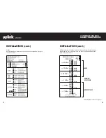
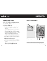
INSTALLATION (cont.)
Input 1 if Standard Type
FIGURE 3: Wiring example for voltage trip
Voltage Trip -
Input 1 if set for standard input can be tripped by applying 12 V to the +
input and 0 V to the - input. A signal must be continuously present for 500 ms.
FIGURE 4: Wiring example for open collector trip
Open Collector -
Inputs 1 if set for standard input can be tripped by applying 12 V to the
+ input and the Open Collector output of the panel to the - input. A signal must be
continuously present for 500 ms.