16
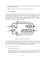
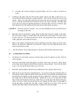
even exposure is obtained by linking the laser control pulses with the movement of the
motion system. In this way the number of pulses per unit of travel can be made constant
and even exposure of the material to laser radiation can be obtained. In proportional
mode the pulse rate of the laser control signal is defined in pulses per unit of travel. The
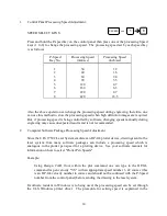
lower left corner of the display will indicate "P" if proportional pulse mode is active.
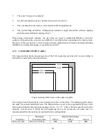
Pulse
Width
Pulse Rate (number of pulses per unit of travel)
Figure showing laser control signal in proportional pulse mode
•
Continuous Pulse Mode (CPM)
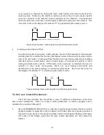
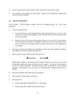
In continuous pulse mode, pulse width and pulse rate are both measured in microseconds
and the pulse rate is defined as the time that elapses between the start of one pulse and the
start of the next pulse. Continuous Pulse Mode may be used when engraving or marking
materials such as coated metals where a higher degree of removal is required; or when
cutting materials such as acrylic. CPM mode can be used only on materials that are not
sensitive to laser beam overexposure which can occur during acceleration and
deceleration of the optical carriage in continuous pulse mode. The lower left corner of
the display will indicate "C" if continuous pulse mode is active.
Pulse
Width
Pulse
Rate
Figure showing laser control signal in continuous pulse mode
To Set Laser Control Parameters:
The ULS Laser Systems have the ability to store 10 different combinations of the three
laser control parameters. Each set of laser control parameters is called a program and is
identified by a number 0 through 9.
1.
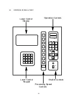
Press the PROGRAM SELECT key to enter laser control program mode (the laser control
program number in upper left corner of display will blink) and select a program number 0
through 9 on the keypad. The program number selected will appear blinking in the upper
left corner of the display panel and the laser control parameters are then entered as
follows:


