background image

 
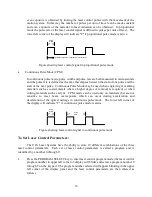
11.  Turn on the laser system power switch. 
 
Laser processing (engraving) can normally begin at this point. 
 
See  SECTION  3  -  OPERATION  for  procedures  for  focusing  laser  beam  and  setting  laser 
controller parameters. 
 

2.2.1  VETILATIO PROCEDURE 

 
To properly exhaust fumes and smoke from the material surface during lasing, 400 cfm minimum 
is  required  at  the  point  of  4  inch  connection  to the system.  Use maximum diameter rigid duct 
work from the roof or down the wall.  Reduce the duct work to four inches just before the point 
of attachment to the laser system. 
 
Locate laser system where a straight run to the ventilator can be achieved. Duct work should be 
as  short  as  possible  between  the  ventilator  and  the  laser  system.    Flexible  ducting  can  be  used 
from the laser system to rigid duct work. 
 
Ventilator should be equipped with an on/off switch and wired in accordance with local electrical 
codes.  We recommend plugging the laser system into a 110V switched outlet, controlled by the 
on/off switch for the ventilator, to ensure laser system cannot be operated without the ventilator.  
It is also advisable to power the laser system through a surge protector to prevent damage to the 
electronics and laser. 
 
Installation  of  the  ventilation  system  should  comply  with  all  applicable  local  and  government 
regulations.  We recommend the use of licensed contractors for installation of the equipment. 

 
2.2.2  DIP SWITCH SETTIGS 

 
There  are  two  dip  switch  blocks  on  the  main  control  board  for  the  laser  system  and  the  cover 
must  be  removed  to  access  them.    Each  block  contains  ten  switches  and  the  two  blocks  are 
referred to as Dip Switch one and two. 
 
1. 

Dip Switch 1 - Located on the right side of the system (under top enclosure) on the printed 
circuit  board  with  the  parallel  and  serial  interface  connections.    Dip  Switch  1,  marked 
"DSW1", has 10 small switches, and is located next to parallel interface connection. 


This  switch  is  used  to  select  the  interface  (parallel  or  serial),  set  field  size,  and character 
font, etc.  For details refer to "Dip Switch Setting Table" in Appendix A. 

 
2. 

Dip Switch 2 - Located on the right side of the system (under top enclosure) on the printed 
circuit  board  with  the  parallel  and  serial  interface  connections.    Dip  Switch  2,  marked 
"DSW2", has 10 small switches, and is located next to Dip Switch 1. 


Содержание ULS1750C

Страница 1: ...OPERATIO A D MAI TE A CE MA UAL U IVERSAL LASER SYSTEMS Model ULS1750C Universal Laser Systems Inc 7707 East Acoma Drive Scottsdale AZ 85260 602 483 1214 Volume I Rev 3 April 1992...

Страница 2: ...EDURE 9 3 2 CONTROL PANEL LAYOUT 10 3 3 OPERATION CONTROLS 11 3 4 SHUTTER CONTROLS 13 3 5 PROCESSING SPEED CONTROLS 13 3 6 LASER CONTROLS 15 3 7 SOFTWARE CONTROLLED POWER CHANGE optional 18 3 8 FOCUSI...

Страница 3: ...ACEMENT 41 4 9 1 X AXIS BEARING ADJUSTMENT 41 4 9 2 Y AXIS BEARING ADJUSTMENT 42 4 9 3 X AXIS BEARING REPLACEMENT 44 4 9 4 Y AXIS BEARING REPLACEMENT 45 4 10 SET SCREW ADJUSTMENT 47 4 10 1 X AXIS 47 4...

Страница 4: ...the written permission of Universal Laser Systems Inc OTICE Universal Laser Systems Inc does not assume any liability arising out of the application or use of any products circuits or software descri...

Страница 5: ...wide range of parameters for material processing Class I safety enclosure Fast X Y laser beam positioning system for quality laser processing at high speed Large material processing area Extended vert...

Страница 6: ...e laser beam before it enters the work area Shutter control is located on the lower right corner of the system control panel When the shutter switch is open the LED is on If any interlocked doors are...

Страница 7: ...the machine All CDRH required labels are properly affixed to the machine in the appropriate locations at the time of manufacture These labels are not to be removed If they become damaged or removed fo...

Страница 8: ...moved the terminals of the interlock connector at the front of the enclosure are no longer in contact and the laser beam will be blocked by the shutter A shorting plug called an interlock defeat tool...

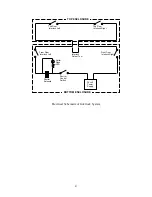
Страница 9: ...id Shutter Control Switch Sutter Open LED Front Door Interlock Left Front Door Interlock Right Top Door Interlock Left Top Door Interlock Right TOP ENCLOSURE BOTTOM ENCLOSURE Interlock Defeat Tool Ele...

Страница 10: ...outlets only Do not defeat the ground connection under any circumstances When the power is turned on the automatic origin setting operates and the arm and focusing optics carriage move Keep hands or o...

Страница 11: ...be found on the left side of the machine b Ensure that the power cord is removed and gently lift the cover up and off of the machine This will require two people to accomplish Watch out for the one i...

Страница 12: ...erated without the ventilator It is also advisable to power the laser system through a surge protector to prevent damage to the electronics and laser Installation of the ventilation system should comp...

Страница 13: ...serial interface connection refer to the Dip Switch Setting Table in Appendix A and set the DIP switch settings to match the settings required by the software being used 2 2 4 RS 232 SERIAL CABLE CO...

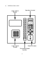
Страница 14: ...rocessed 4 Adjust focus reference Section 3 8 5 Close all access doors 6 Set laser controller parameters reference Section 3 6 7 Set the processing speed reference Section 3 5 can also be set from sof...

Страница 15: ...SE WIDTH RATE PULSE SELECT PROGRAM 1 2 3 4 5 6 7 8 X POSITION Y POSITION P P MODE 2 1 ENTER REPEAT REPEAT VIEW PAUSE P SPEED FAST AUX TEST SHUTTER OPEN CLOSED POWER Laser Control Keypad Processing Spe...

Страница 16: ...n with the Test key to manually mark lines on material to indicate the edges of the engraving field or as alignment marks VIEW KEY VIEW Pressing this key causes the focusing optics carriage to move to...

Страница 17: ...repeat mode memory OTE The repeat mode will continue to store drawings until it is full the capacity is 1 megabyte If two drawings are sent to the memory the first drawing will be processed followed...

Страница 18: ...are used to open and close the mechanical solenoid driven shutter which blocks the beam and stops it from entering the engraving area The switch will provide power to open and close the shutter and th...

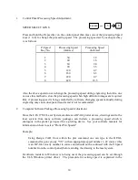
Страница 19: ...ause unexpected results and is not recommended 2 Computer Software Package Processing Speed Adjustment Since the ULS 1750C Laser System emulates an HP GL plotter device drawings sent to the laser syst...

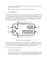
Страница 20: ...ser control signal This LED indicates that Laser Power is on This LED indicates that Power Change option is on see section 3 7 Program Number Pulse Mode Pulse Width Pulse Rate Figure Showing Typical L...

Страница 21: ...h as coated metals where a higher degree of removal is required or when cutting materials such as acrylic CPM mode can be used only on materials that are not sensitive to laser beam overexposure which...

Страница 22: ...he desired pulse settings have been entered into programs to permanently save the programmed settings so that they will not be lost when the laser system is turned off press in rapid sequence the zero...

Страница 23: ...it is best to consult your software manual to find out which colors correspond to which pen numbers in a particular piece of software Many software packages also give the user the ability to assign a...

Страница 24: ...ove the Z axis stage down by turning the crank knob at the top of the system counterclockwise until the flat of the focus tool can be placed flat against the square lens holder d Observe the top of th...

Страница 25: ...ULS 3 10 LASER PROCESSI G AREA The range and maximum processing area of the ULS engraving systems will vary according to the field size selected by the dip switches ANSI B ISO A3 ISO A4 ANSI A Figure...

Страница 26: ...10 20 x 7 83 in OFF ON ON Expanded 431 8 x 297 mm 17 x 11 69 in ON OTE Setting the field size for the Laser System will not guarantee access to the entire field unless the software being used is conf...

Страница 27: ...nfrared spectrum beam is invisible 7 A solenoid operated shutter is located between output of the laser and top compartment of the system In the OFF position the shutter completely blocks the laser be...

Страница 28: ...rn stains either alcohol or acetone may be used to remove residue 8 Move Z stage down to bottom and clean the Z stage guide way with glass cleaner and a paper towel 9 Remove exhaust hose and clean exh...

Страница 29: ...will void the 90 day warranty on these optics OTE Wash hands with soap and water prior to handling optics 4 3 1 TOP E CLOSURE REMOVAL A D REPLACEME T 1 Disconnect the power cord to the machine 2 To r...

Страница 30: ...ical equipment 9 Fold clean lens tissue in fourths then place lens in between the doubled tissue Apply lens cleaning solution 1 to the double thick lens tissue covering the lens using the small plasti...

Страница 31: ...rovided with a durable multilayer coating and will withstand repeated cleanings if care is taken and they are cleaned properly following these instructions 4 3 3 FIRST MIRROR CLEA I G 1 Top Enclosure...

Страница 32: ...plastic wash bottle Let sit for one minute 8 Final cleaning is done by gently wiping using several 100 cotton swabs Soak the lens with lens cleaning solution 1 and then gently roll the swab and wipe t...

Страница 33: ...ble a piece of lens tissue lengthwise and place against the 2 mirror 4 Apply lens cleaning solution 1 to the tissue and mirror using the small plastic bottle The lens tissue should stick to the mirror...

Страница 34: ...surface 7 Replace mirror on the optics by setting mirror and bracket straight down onto the angled portion of the optics holder and screw in the 2 56 screw and washer OTE Sliding mirror on optics hold...

Страница 35: ...m cover from the output end of the replacement laser and install on the defective laser 8 Box the defective laser in the packing box that previously held the replacement laser 4 5 LASER I STALLATIO 1...

Страница 36: ...he front left corner of the machine and the electronics and water lines on the right side of the machine 2 The defeat tool must be inserted into its receptacle in the center of the machine behind the...

Страница 37: ...sing again turns off laser DA GER When the laser is on injuries can occur if a body part is placed in front of the beam Remember the beam is invisible 8 If mirror 1 was previously cleaned move to Step...

Страница 38: ...the opening going to the 3 mirror and should completely cover the test dot burned at P1 If you had no luck in getting the P2 dot to hit the tape then turn the beam on and use the thermal paper to find...

Страница 39: ...If the combined dot is low in the opening then the shutter block must be turned slightly counterclockwise to raise where the P1 and P2 dots are hitting To do this loosen the two nylon tip set screws h...

Страница 40: ...ng to the 4 mirror burn a P2 dot leave beam on Adjust the 3 mirror tube up or down to position the dot correctly Shut off the beam and tighten the 3 mirror tube set screws Recheck the P2 dot position...

Страница 41: ...ack of the machine To move P2 to the left as seen through the 4 mirror move the upper left knob on 2 mirror clockwise and vice versa to move P2 to the right OTE Moving the P2 dot to the left as seen t...

Страница 42: ...et front door hinges loose so door will lay flat against frame when closed If hinges are too tight the door sides will bow just above the hinges 4 8 BELT ADJUSTME T A D REPLACEME T 1 Ensure that the p...

Страница 43: ...ures 2 and 3 11 Ensure front and rear of Y arm is square with calipers reference Figure 7 The Y arm must be square to within 10 thousandths at this point Replace rear support belt keeper with two scre...

Страница 44: ...be found on the left side of the machine b Ensure power cord is removed then gently lift the cover up and off of the machine This will require two people to accomplish Watch out for the one inch mirro...

Страница 45: ...eference Figure 6 5 Remove the two black screws located below the front Y axis motor reference Figure 4 6 Carefully tilt motor so top of motor pulley end tilts towards rear of machine The Y axis belt...

Страница 46: ...nsion screws evenly until a ready of 170 200 gms is needed to pull one belt into contact with the other belt reference Figures 6 and 8 4 Move final focus lens carriage to the rear and recheck tension...

Страница 47: ...aring Replacement section to replace the X axis bearings 10 At this point the Y axis rail moves smoothly left and right on the X axis Hold the Y rail gently in place do not apply pressure up or down a...

Страница 48: ...ing while moving carriage front to rear and rotating cotton swab at the same time 6 When bearings and the two channels are clean gently grasp carriage across lens holder and move back and forth Moveme...

Страница 49: ...Rotate bearing very slightly towards the Y rail i e towards the wide side of the eccentric using the socket Hold the socket still with your fingers then insert the 1 Phillips through the socket and ti...

Страница 50: ...e the front X axis rail rearward enough about one inch to disengage the rear of the Y axis arm from the rear X rail 7 Slide the Y axis arm off of the front X rail and set the front X rail down Be care...

Страница 51: ...tipped set screws are not sticking If they are sticking refer to the Set Screw Adjustment section before proceeding CAUTIO Uneven pressure or excessive pressure on the carriage can damage all bearings...

Страница 52: ...and put through the brass bearing 16 Install screw just snug then back it off about 1 8 of a turn 17 Turn eccentric the 7mm socket by hand Turn the nut just enough to remove all side to side play in...

Страница 53: ...1 32 of an inch reference Figures 11a and 11c 7 Gently rotate entire Y rail left and right and check for excessive play Excessive play is any movement greater than approximately 1 64 to 1 32 of an inc...

Страница 54: ...reference Figure 10A 8 Gently move final focus lens carriage base in right hand up and down and check for excessive play Excessive play is any movement up and down greater than approximately 1 64 of a...

Страница 55: ...ll Pulse Width and Pulse Rate applied to the laser whenever power to the system is turned on The function of tickle is to keep the gas plasma in the laser warmed up at all times to help the laser resp...

Страница 56: ...ore c Depress keypad 1 OTE Make sure that the 0 Store 1 keys are pressed rapidly or the machine will not enter the tickle setting mode The display changes from Pulse Width 200 and Pulse Rate 2000 to a...

Страница 57: ...the same intensity If all the dots appear even and visible tickle is properly set If when starting a line of marking some dots are missing the Pulse Rate will have to be changed Tickle Pulse Rate Sett...

Страница 58: ...there are none missing repeat steps 18a through 20 but increase Pulse Rate by five until dots start to become uneven or missing then lower Pulse Rate by five If you had to increase Pulse Rate to stabi...

Страница 59: ...ion of the work performed and materials used will be included with the equipment 5 2 OUT OF WARRA TY SERVICE The procedure for out of warranty service is the same as that for in warranty service excep...

Страница 60: ...ONT INTERFACE EXPAND FIELD KANJI MODE MODE DISABLED SERIAL PARALLEL ANSI ASCII I SPANISH LATIN ISO GERMAN ISO SPANISH ANSI ASCII 2 ISO SWEDISH NAME ISO FRENCH ISO PORTUGUESE 9 10 ANSI A ANSI B ISO A3...

Страница 61: ...ff see DSW1 Switch 6 DSW2 1 8 Used to setup the serial interface communication parameters DSW2 9 OFF sets the command mode to RD GL I This switch should always be in the OFF position The default switc...

Страница 62: ...s Serial RS 232C Manual Speed Selection 8 Stage Commands HP GL RD GL1 Buffer Memory Size 1MB System Dimensions 45 x38 x21 System Weight 208 lbs Safety Classification Class I Support Table Dimensions 1...

Страница 63: ...58 Specifications are subject to change without notice...

Страница 64: ...300 P 19999 C 1000 this is continuous mode Wood V 5 O 300 P 10000 to 19999 Note Parameters must be adjusted according to density of engraving and style of font image Enamel Coated Brass V 1 V 1 O 300...

Страница 65: ...60 Engraving Plastic micro surface V 5 O 75 P 19999 Engraving Plastic medium V 5 O 400 P 15000 to 19999 Engraving Plastic reverse V 5 O 250 P 10000 Note Focus should be at 2 8...

Отзывы: