background image

V130-33-B1 Installation Guide

2

Unitronics 

Additional product documentation is in the Technical Library, located at 

www.unitronics.com

and on 

the Unitronics’ Setup CD. 

Technical support is available at the site, and from [email protected]


Standard Kit Contents 

Vision controller 

Mounting brackets (x2) 

Power supply connector 

Rubber seal 

Battery (installed) 

Unitronics’ Setup CD 

Programming cable + RS232 adapter 


Danger Symbols 

When any of the following symbols appear, read the associated information carefully. 

Symbol Meaning  Description 

Danger 

The identified danger causes physical and property damage. 

Warning 

The identified danger could cause physical and property damage. 

Caution

 Caution  Use 

caution. 

Before using this product, the user must read and understand this document. 
All examples and diagrams are intended to aid understanding, and do not guarantee operation. 
Unitronics accepts no responsibility for actual use of this product based on these examples. 
Please dispose of this product according to local and national standards and regulations. 
Only qualified service personnel should open this device or carry out repairs. 

Failure to comply with appropriate safety guidelines can cause severe injury or property damage.

Do not attempt to use this device with parameters that exceed permissible levels. 
To avoid damaging the system, do not connect/disconnect the device when power is on. 

Environmental Considerations 
 

Do not install in areas with: excessive or conductive dust, corrosive or flammable gas,  
moisture or rain, excessive heat, regular impact shocks or excessive vibration, in accordance 
with the standards given in the product’s technical specification sheet. 

Ventilation: 10mm space required between controller’s top/bottom edges & enclosure walls. 
Do not place in water or let water leak onto the unit. 
Do not allow debris to fall inside the unit during installation. 
Install at maximum distance from high-voltage cables and power equipment. 

Содержание Vision OPLC V130-33-B1

Страница 1: ...his mode enables you to View Edit operand values COM port settings RTC and screen contrast brightness settings Stop initialize and reset the PLC To enter Information Mode press the i button for several seconds Programming Software Utilities The Unitronics Setup CD contains VisiLogic software and other utilities VisiLogic Easily configure hardware and write both HMI and Ladder control applications ...

Страница 2: ...onics accepts no responsibility for actual use of this product based on these examples Please dispose of this product according to local and national standards and regulations Only qualified service personnel should open this device or carry out repairs Failure to comply with appropriate safety guidelines can cause severe injury or property damage Do not attempt to use this device with parameters ...

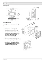
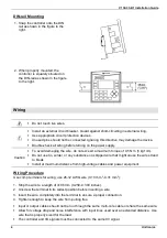
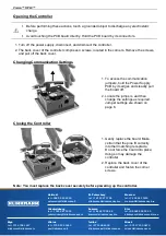
Страница 3: ...ller into the cut out ensuring that the rubber seal is in place 3 Push the 2 mounting brackets into their slots on the sides of the controller as shown in the figure to the right 4 Tighten the bracket screws against the panel Hold the bracket securely against the unit while tightening the screw 5 When properly mounted the controller is squarely situated in the panel cut out as shown in the figure ...

Страница 4: ... kgf cm Do not use tin solder or any substance on stripped wire that might cause the wire strand to break Install at maximum distance from high voltage cables and power equipment Wiring Procedure Use crimp terminals for wiring use 26 12 AWG wire 0 13 mm 2 3 31 mm2 1 Strip the wire to a length of 7 0 5mm 0 250 0 300 inches 2 Unscrew the terminal to its widest position before inserting a wire 3 Inse...

Страница 5: ...wer supply connect one end of a 14 AWG wire to the chassis signal connect the other end to the panel Note If possible the wire used to earth the power supply should not exceed 10 cm in length However it is recommended to earth the controller in all cases Communication Port Turn off power before making communications connections Caution Signals are related to the controller s 0V the same 0V is used...

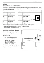
Страница 6: ...gnal 4 RS232 signal 5 0V reference 5 RS232 signal 6 DSR signal 6 B signal Pin 1 Standard programming cables do not provide connection points for pins 1 and 6 When a port is adapted to RS485 Pin 1 DTR is used for signal A and Pin 6 DSR signal is used for signal B RS232 to RS485 Jumper Settings The figure to the right shows the jumper factory default settings RS232 RS485 termination ON Note that in ...

Страница 7: ...ntroller 1 Gently replace the board Make certain that the pins fit correctly into their matching receptacle Do not force the board into place doing so may damage the controller 2 Replace the back cover of the controller and fasten the corner screws Note You must replace the back cover securely before powering up the controller Samara tel 7 846 273 95 85 samara klinkmann spb ru Yekaterinburg tel 7 ...

Отзывы: