9
OPERATING INSTRUCTIONS - continued
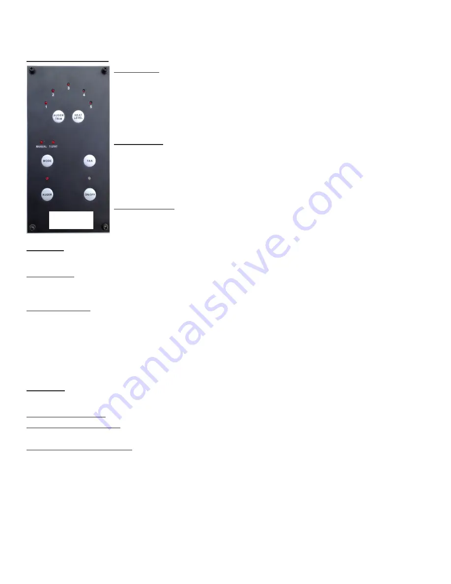
Control Board Functions:
MODE Button:
The MODE button allows you to switch operating mode on your pellet stove room heater.
Depress the MODE button to switch between Manual and T-STAT modes. As you depress the MODE but-
ton, the indicator light above the desired mode will engage. When you engage the Manual mode, you will
be able to manually select the heat settings. If you have installed a remote thermostat for your heater and
wish to have the heater controlled by that thermostat, depress the MODE button to engage T-STAT mode.
The thermostat will control the heat output of the heater alternating between the lowest heat level and the
highest heat level that you have pre-selected. The T-STAT mode provides the most even heat output, for bet-
ter comfort, and to extend the life of the pellet fuel ignition system. Additionally, the constant flame serves as
a warning for people and pets to keep away from the heater while it is in operation.
ON/OFF Button:
The ON/OFF button is used to turn the heater on and off. Whenever there is power to the
heater, the LED indicator light above the ON/OFF button will be solid red. If the heater is cold prior to start-up,
press and release the ON/OFF button. The LED light above the ON/OFF button will alternately flash red and
green to indicate the startup cycle has started. Fuel pellets will start to feed into the burn pot and the pellet fuel
ignition system will be activated. Flames in the burn pot will normally appear between 4 - 8 minutes, and once
the flame has been established, the startup cycle will end, this takes between 8-12 minutes. At this point the
LED indicator light above the ON/OFF button will glow solid green. The user will now be able to make heat level
adjustments.
HEAT LEVEL Button:
Depress the HEAT LEVEL button to advance the heat level by one level until you reach the
maximum setting; from the maximum level you will decrease one level each time you depress the HEAT LEVEL button.
The circulation fan speed will also increase with the heat level setting. Wait until the startup cycle is complete and the
ON/OFF LED is solid green to set Heat Level. (The HEAT LEVEL LEDs are also used as codes to indicate a malfunc
-
tion, please refer to the
Safety Features and warning codes
section for more information.)
FAN Button:
Depressing the FAN button will set the circulation fan speed to high, overriding the automatic fan speed control. The onboard
logic will modulate the fan speed in accordance with the heat level setting. It is recommended that you allow the control to automatically set and
adjust the speed of the fan to obtain optimum efficiency and minimal fan noise.
AUGER Button:
Whenever Operating the Pellet Stove for First Time, or if The Stove Runs Out Of Pellets, it is Necessary to Prime the Auger
with Pellet Fuel. To do this, Press and Hold the AUGER Button for Approximately 3 Seconds until the AUGER LED illuminates. This Procedure
will prime the Auger and then Automatically Initiate the Normal Ignition Cycle.
NOTICE: Do not use this procedure for normal startup. To
do so would cause excessive fuel build-up in the burn pot.
AUGER TRIM Button:
This Button is only enabled when operating at Heat Level 1. Depress the AUGER TRIM Button to change the Auger feed
rate on the minimum heat level to account for the quality of pellet fuel being used. Increasing the Auger feed rate will help keep the flames
from extinguishing on the minimum heat level setting. You can also use the AUGER TRIM button to lower heat output on the minimum heat
level setting:
Ø
Depress and release the AUGER TRIM button until the heat level 1 and 5 setting lights appear to slightly increase the feed rate on the
minimum heat level.
Ø
Depress and release the AUGER TRIM button until the heat level 1 and 4 setting lights appear to slightly reduce the pellet feed rate on the
minimum heat level setting. Use this setting to reduce the heat level output on low.
Ø
Depress and release the AUGER TRIM button until only the heat level 1 setting light is on, this is the factory setting and works for most
types of fuel.
Open Door:
During normal operation the heater will automatically shut off if the viewing door is opened for more than 30 seconds. This
action causes the heater to go into vacuum error mode. To clear this error and restart the heater, close the door, depress the ON/OFF button
and then follow directions for restarting heater.
Refilling the Fuel Hopper:
For maximum performance do not let the pellet fuel hopper drop below 1/4 full.
Fuel Hopper Lid Safety Switch:
When the Fuel Hopper Lid is opened the auger will stop turning to prevent accidental injury.
KEEP PELLET FUEL HOPPER LID CLOSED AT ALL TIMES EXCEPT WHEN REFILLING. DO NOT OVERFILL HOPPER.
Safety Features and warning code:
1. Your heater is equipped with a temperature “high-limit” switch, designed to shutdown the auger in case of an over temperature situation. The
high-limit switch is a thermo snap disc type and must be manually reset in the event of an overheat shutdown. Once the heater has cooled
down, you can reactivate the high-limit switch by depressing the manual reset button located on the high-limit switch.
2. When the High-Limit switch opens, which indicates an overheat failure, the HEAT LEVEL LED’s 3 & 4 will flash red.
3. Your heater is equipped with a vacuum switch that automatically shuts down the auger in the event of a exhaust fan malfunction.
4. When a Vacuum Error is sensed, the HEAT LEVEL LED’s 1 & 2 will flash red. Check to ensure the glass door is latched properly.
5. When the Low-Limit switch opens, (fire went out) the HEAT LEVEL LED’s 4 & 5 will flash red. First check fuel supply, then check to
ensure Auger is not jammed and finally that pellet hopper door is properly closed.
6. When the Pellets in the Burn Pot fail to ignite HEAT LEVEL LED’s 1 & 5 will flash red.
NOTE: In the event that the high-limit switch or vacuum switch activates, please contact your dealer to discuss the cause of this
activation and to ensure that your heater continues to operate in a safe manner. Either switch tripping can indicate a problem with
the operation of your heater.
Figure 3
Содержание 5560 (I)
Страница 25: ...25 VENT TERMINATION LOCATIONS Figure 22...


