12
INSTALLING YOUR ROOM HEATER
You have already made the important decision of choosing your U.S. Stove Pellet Burning Room Heater; now your next step
is to determine where to install your new pellet stove heater. To get the most efficient use of re-circulated heat, you should
consider a room that is centrally located within your home. Choose a room that is large and open.
It is
Extremely Important
to maintain proper clearances from any combustible surfaces or materials in the room where your
heater will be located. You can find proper clearance measurements on page 13 of this manual and on the rating label of
your pellet stove.
The pellet stove can be vented through an exterior wall or into an existing masonry or metal chimney. The chimney must
be lined if it is over 6” (150mm) in diameter or if it has a cross-sectional area of over 28 square inches (711mm2). Venting
can pass through the ceiling and roof if approved pipe is used. Where passage through a wall, or partition of combustible
construction is desired, the installation must conform to CAN/CSA-B365
DO NOT OBTAIN COMBUSTION AIR FROM THE ATTIC, GARAGE OR ANY OTHER UNVENTILATED AREA. YOU MAY
OBTAIN COMBUSTION AIR FROM A VENTILATED CRAWLSPACE.
DO NOT INSTALL A FLUE DAMPER IN THE EXHAUST VENTING SYSTEM OF THIS UNIT.
DO NOT CONNECT THIS UNIT TO A CHIMNEY FLUE SERVING ANOTHER HEATER, FURNACE OR APPLIANCE.
INSTALL VENT AT CLEARANCES SPECIFIED BY THE VENT MANUFACTURER.
ONLY USE APPROVED MATERIAL FOR INSTALLATION, FAILURE TO DO SO MAY RESULT IN PROPERTY DAMAGE,
BODILY INJURY, OR EVEN DEATH.
This appliance is certified for use with listed 3 inch or 4 inch “PL” or “L” pellet venting products as well as Selkirk’s Direct-
Temp Vent system for pellet burning appliances. The use of other components other than stated herein could cause bodily
harm, heater damage, and void your warranty.
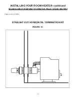
HORIZONTAL EXHAUST VENT INSTALLATION
1. Locate your pellet stove in a location which meets the requirements of this manual, but in an area where it does not
interfere with the house framing, wiring, etc.
2. Install a non-combustible hearth pad underneath the pellet stove. This pad should extend at least 6” (152mm) in front
of the unit.
3. Place the pellet stove approximately 15” (381mm) away from the interior wall.
4. Locate the center of the exhaust pipe of your unit. This point should then be extended to the interior wall of your house.
Once you have located the center point, on the interior wall, cut a 7” (175mm) diameter hole through the wall.
5. The next step is to install the wall thimble, refer to the instructions which come with the wall thimble for this step.
6. Install the appropriate length of exhaust vent pipe into the wall thimble. See step 11 when determining the correct
length of exhaust vent to use.
7.
Outside Fresh Air is Mandatory when installing this pellet stove room heater in airtight homes and mobile
homes.
Be sure that the outside air vent has an approved cap on it to prevent rodents from entering. Be sure to install
in location that won’t become blocked with snow, etc.
8. The air intake pipe is equipped with a butterfly valve that is preset to maximum air intake. For optimum operating ef
-
ficiency you may calibrate the butterfly valve to provide less intake air. (See Figure 7)
Caution: Too much restriction
on the intake air will cause dirtier burn, therefore, will require more frequent cleaning.
9. Connect the exhaust vent pipe to the exhaust outlet of your pellet stove.
10. Secure all vent joint connections with 3 screws. Seal the exhaust vent joint connections with high temperature silicone
sealant.
11. Push the unit straight back to the interior wall, being sure to maintain the minimum clearances to combustibles 6”
(152mm) to the back of the unit. Seal the annular space of the wall thimble and around the vent pipe with high tem
-
perature silicone sealant.
12. The exhaust vent pipe must extend at least 12” (300mm) out past the exterior wall. Seal the annular space of the wall
thimble and around the vent pipe with high temperature silicone sealant.
13. Install an approved horizontal termination cap or if necessary install a 90° elbow and appropriate length of vertical vent
-
ing. An approved vertical vent cap is recommended.
Содержание 5560 (I)
Страница 25: ...25 VENT TERMINATION LOCATIONS Figure 22...


