


035-18550-001-A-0902
4
Unitary Products Group
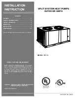
GENERAL
These heat pump units are designed for outdoor instal-
lation on a roof or at ground level. Every unit is com-
pletely piped and wired at the factory and is shipped
ready for immediate installation. Only the liquid and
vapor lines to the indoor coil, the control wiring and the
main power wiring are required to complete the instal-
lation. Each unit is dehydrated, evacuated, leak tested
and pressure tested at 450 psig before being pressur-
ized with a holding charge of Refrigerant-22 for ship-
ment and/or storage.
Every unit includes a heavy-duty compressor with line
break overload protection, a suction line accumulator,
a 4-way reversing valve, filter-drier, expansion valves,
distributors, check valves, and a copper tube/aluminum
fin coil.
All controls are readily accessible for maintenance,
adjustment and service. All power and control wiring
can be routed through the front of the unit.
SAFETY CONSIDERATIONS
Installer should pay particular attention to the words:
NOTE, CAUTION and WARNING. Notes are intended
to clarify or make the installation easier. Cautions are
given to prevent equipment damage. Warnings are
given to alert the installer that personal injury and/or
equipment damage may result if the installation proce-
dure is not handled properly.
REFERENCE
This instruction covers the installation of the outdoor
unit. For information on the matching indoor, see PN#
035-18877-001.
All accessories come with a separate installation man-
ual. Refer to Parts Manual for complete listing of
replacement parts on this equipment.
The above forms may be ordered from:
Standard Register
2101 W. Tecumseh Rd
Norman, Oklahoma 73069
Toll Free Tel. 877-318-9675
Toll Free Fax. 877-379-7920
AGENCY APPROVALS
Design certified by UL as follows:
1.
For use as a cooling/heat pump unit only.
2.
For outdoor installation only.
INSPECTION
As soon as a unit is received, it should be inspected for
possible damage during transit. If damage is evident,
the extent of the damage should be noted on the car-
rier's freight bill. A separate request for inspection by
the carrier's agent should be made in writing. See Form
50.15-NM for more information.
Improper installation may create a condition
where the operation of the product could cause
personal injury or property damage.
Improper installation, adjustment, alteration,
service or maintenance can cause injury or
property damage. Refer to this manual for
assistance or additional information, consult a
qualified installer or service agency.
This product must be installed in strict compli-
ance with the enclosed installation instructions
and any applicable local, state, and national
codes including, but not limited to, building,
electrical, and mechanical codes.
Содержание EF-10
Страница 22: ...035 18550 001 A 0902 22 Unitary Products Group...
Страница 23: ...035 18550 001 A 0902 Unitary Products Group 23...


