


PowerWAVE 9000 DPA UPS - Multi-Cabinet Configuration
6-5
(Issue 2.1 Oct. 2009)
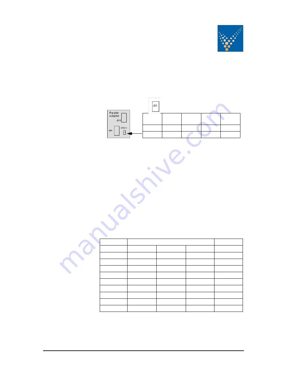
cables between the cabinets will be connected through the connectors JD5
and JD6.
NOTE: Set the Switch SW2-2 correctly according to the
corresponding cabinet configuration.
6.2.4 DIP-Switch SW1-9 Settings
Before starting up the parallel system it is necessary to set the DIP Switches
SW1-1 and SW1-9 to their correct positions.
6.2.5 DIP Switch SW1-9
The DIP Switch SW1-9 is located on every Cabinet With this switch it is
possible to determine the “position of a DPA Cabinet” in a Multi-Cabinet
Chain. Define each DPA- Cabinet in a Multi-Cabinet Chain as:
1.
The “First”,
2.
The “Middle” (there may be more than one) and
3.
The “Last”
Cabinet in the Multi-Cabinet Chain by setting the DIP Switch SW1-9 on
each cabinet according to the Table below:
Having set the SW1-9 on all the DPA Cabinets correctly the UPS’s may be
commissioned
DIP Switches position on PCB NW8141
First UPS
Other UPS
Last UPS
Single UPS
SW 1a 1
ON
OFF
ON
ON
SW 1b 2
OFF
OFF
ON
ON
SW 1c 3
ON
OFF
OFF
ON
SW 1d 4
ON
OFF
ON
ON
SW 1e 5
ON
OFF
ON
ON
SW 1f 6
ON
OFF
ON
ON
SW 1g 7
ON
OFF
ON
ON
SW 1h 8
ON
OFF
ON
ON
SW 1i 9
ON
OFF
ON
ON
Single
Unit
First
Unit
Middle
Unit
Last
Unit
SW1
ON
OFF
OFF
ON
SW2
ON
ON
OFF
OFF
Содержание PowerWAVE 9000 DPA
Страница 4: ......
Страница 12: ...1 4 PowerWAVE 9000 DPA UPS Safety Issue 2 1 Oct 2009 ...
Страница 90: ...8 4 PowerWAVE 9000 DPA UPS Troubleshooting Issue 2 1 Oct 2009 ...
Страница 104: ...10 8 PowerWAVE 9000 DPA UPS Specifications Issue 2 1 Oct 2009 ...


