PowerWAVE 9000 DPA UPS - Operation
4-5
(Issue 2.1 Oct. 2009)
4.3 Description of the LCD
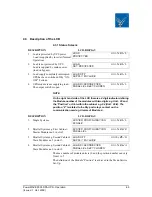
4.3.1 Status Screens
NOTE
On the right hand side of the LCD there is a 4 digit indicator defining
the Module number of the modules with two digits e.g Unit : 06 and
the “Position” or Slot within the cabinet e.g. 04 (Unit : 06/4). The
position “4” is related to the Dry port relays contact on the
communication card eg. Alarms of Module 4.
The max number of module units is 10 and the position number can vary
from 1 to 5.
The definition of the Module “Position” is achieved in the Menu Service
Set-Up.
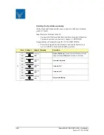
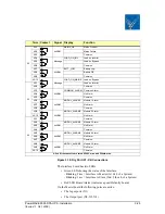
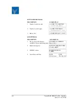
DESCRIPTION
LCD-DISPLAY
1.
Load is protected by UPS power
Load is supplied by inverter (Normal
Operation).
LOAD
PROTECTED
Unit:01/1
2.
Load is not protected by UPS
Load is supplied by mains power
(load on bypass).
LOAD
NOT PROTECTED
Unit:01/1
3.
Load supply completely interrupted.
UPS has been switched off by “ON/
OFF” buttons.
LOAD OFF
SUPPLY FAILURE
Unit:01/1
4.
UPS/module is not supplying load.
The output switch is open
LOAD DISCONNECTED
PARALLEL SWITCH OPEN
Unit:01/1
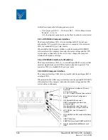
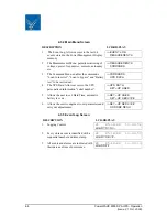
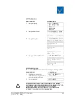
DESCRIPTION
LCD-DISPLAY
1.
Single Systems.
SYSTEM CONFIGURATION
SINGLE
Unit:01/1
2.
Parallel System eg. First Cabinet/
Master Modules no 2 in slot 2.
SYSTEM CONFIGURATION
PARALLEL
Unit:02/2
3.
Parallel System eg. Second Cabinet/
Slave Modules no 5 in slot 3.
LOAD OFF
SUPPLY FAILURE
Unit:05/3
4.
Parallel System eg. Second Cabinet/
Slave Modules no 6 in slot 2.
LOAD DISCONNECTED
PARALLEL SWITCH OPEN
Unit:06/4
Содержание PowerWAVE 9000 DPA
Страница 4: ......
Страница 12: ...1 4 PowerWAVE 9000 DPA UPS Safety Issue 2 1 Oct 2009 ...
Страница 90: ...8 4 PowerWAVE 9000 DPA UPS Troubleshooting Issue 2 1 Oct 2009 ...
Страница 104: ...10 8 PowerWAVE 9000 DPA UPS Specifications Issue 2 1 Oct 2009 ...

