background image

4520362-1/0606

Page 1 - 6 - Operation

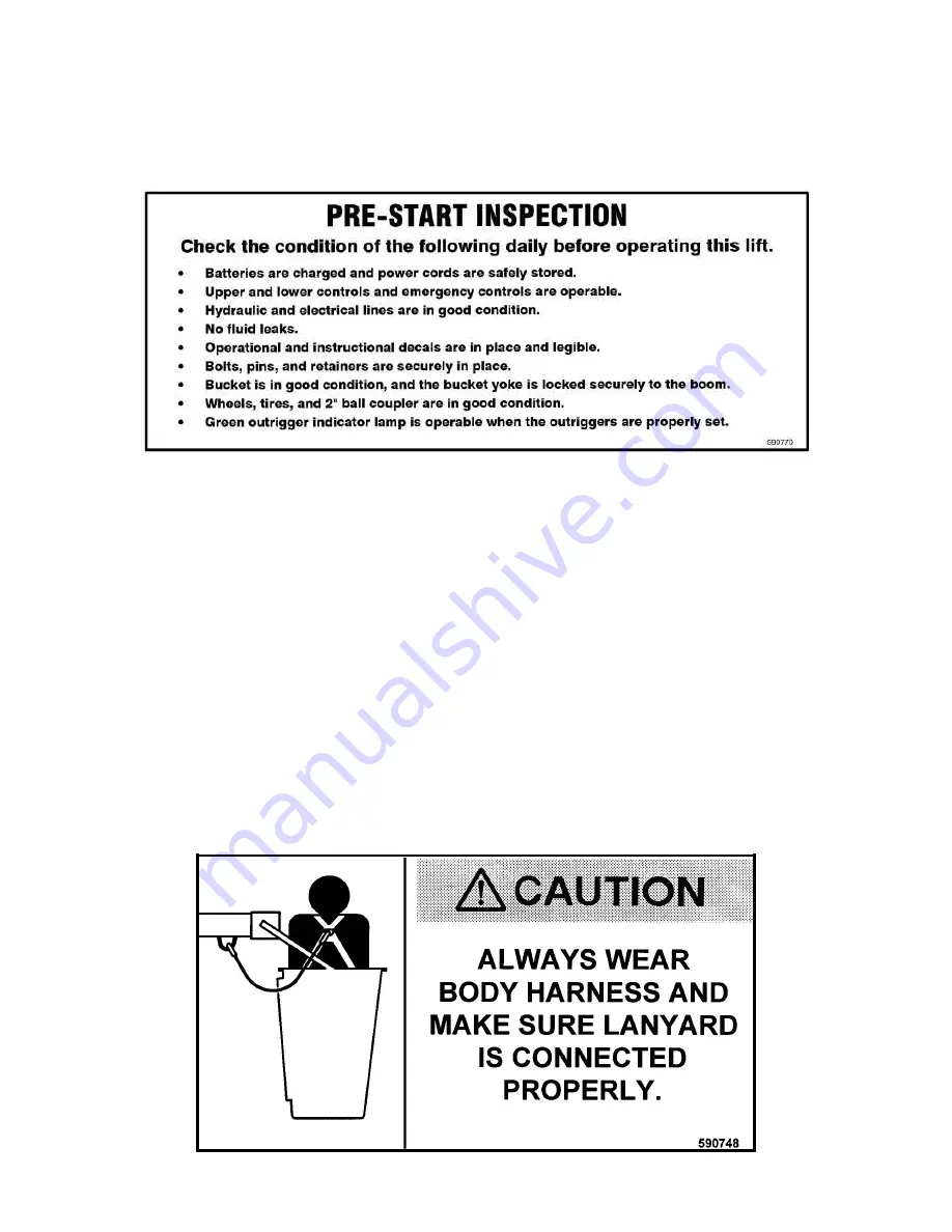
PRE-START INSPECTION

Prior to each days operation, the operator shall check for defects using the Pre-Start Inspection list.

GRAVITY LEVELED BUCKET LOCK

The bucket is gravity leveled and hydraulically dampened, with a positive bucket-locking knob that prevents swinging of the
bucket after it has been placed in a working position.  This locking mechanism is located inside the bucket to the operator's right
when facing the platform control station.  To lock the bucket, turn the locking knob CW until tight.  To release the bucket lock,
rotate knob CCW. 

BUCKET OPERATION

After the trailer has been properly parked and outriggers properly extended and set, disconnect the boom tie-down strap and turn
the key switch to “ENABLE” 

(remember the 5-second timeout on startup).

  The green light on the Lower Control Station will

be lit.  Using the Lower Control Station, raise the lower boom (raising the lower boom will bring the bucket down) until the bucket
is about a foot off the ground.  Check to make sure that the bucket is properly installed.  Check both bucket-yoke lock pins to
insure they are positioned in the holes, and the bucket yoke is securely locked to the boom.

IMPORTANT:  A body harness with a 6 ft. lanyard (p/n: 532053) is furnished with each machine.  DO NOT use a body
harness unless it is designed to meet the appropriate standards and has a 6 ft. lanyard - NO EXCEPTIONS!

Put on the body harness and enter the bucket.  Attach the hook to the "D" ring on the underside of the boom.

Courtesy of Crane.Market 

Содержание 542KB

Страница 1: ...Universal Crane and Personnel Lif t OPERATOR S MANUAL A PRODUCT OF UniLift 850 State Hwy 55 Brooten MN 56316 www ChampUniLift com Publication No 4520362 1 0606 Courtesy of Crane Market...

Страница 2: ...Courtesy of Crane Market...

Страница 3: ...electrical power cords are safely stored to prevent tangling or crushing 6 Always wear the proper body harness and keep the harness secured to the lanyard ring whenever operating the 542KB UniLift fro...

Страница 4: ...erstand the use of the Emergency Manual Lowering Valve and other emergency procedures I will not attempt to alter or disable any safety devices guards or interlocks I have been shown the location of t...

Страница 5: ...rt Inspection 1 6 Bucket Lock 1 6 Bucket Operation 1 6 Crane Operation 1 7 Shutdown 1 7 System Recharging 1 8 Emergency Controls 1 8 EMERGENCY PROCEDURES 2 1 Platform Control Station Switch Failure 2...

Страница 6: ...This page left intentionally blank Courtesy of Crane Market...

Страница 7: ...ing basic components Figure i 1 Self Leveling UniLift With Personnel Bucket Attached ADJUSTABLE OUTRIGGERS Outriggers are used for absorption of tipping load during use and are manually set Adjustable...

Страница 8: ...ction and Maintenance for more details on battery system HYDRAULIC LIFT CYLINDERS Aerial lift is provided by two 3 1 2 inch 88 9 mm double acting cylinders the lower lift cylinder is attached to the l...

Страница 9: ...S THIS UNIT IS NOT INSULATED FROM ELECTRIC SHOCK DEATH OR SERIOUS INJURY TO OPERATORS AND OR BYSTANDERS CAN RESULT FROM CONTACT WITH ELECTRICAL WIRES Description Page i 3 UNIVERSAL CRANE An anchor poi...

Страница 10: ...m Operating Pressure 1450 PSI 10 0 MPa At point where boom hook is 8 feet from center of rotation Unit with Jack Type outriggers MINIMUM VEHICLE TIPPING LOAD HORIZONTALLY EXTENDED On level ground 1 1...

Страница 11: ...lbs Always connect the lights and safety chains and use safe towing practices For maximum safety limit the towing speed to 45 mph 72 km h or less The booms must be stored in the boom cradles when the...

Страница 12: ...s on one outrigger then proceed to the next outrigger DO NOT OVER EXTEND ANY ONE OUTRIGGER OUTRIGGERS MUST BE LOWERED EVENLY AND IN SEQUENCE The unit must be level with the weight of the unit supporte...

Страница 13: ...are fully re engaged 4 Press the power jack switch UP until the front of the UniLift is above level This can be determined by watching the position of the tongue On the front outriggers disengage pin...

Страница 14: ...4520362 1 1106 Page 1 2B Operation Power jack instructions Courtesy of Crane Market...

Страница 15: ...outrigger foot Crank all 4 outriggers evenly Raise the unit 2 3 holes on one outrigger then proceed to the next outrigger DO NOT OVER EXTEND ANY ONE OUTRIGGER OUTRIGGERS MUST BE LOWERED EVENLY AND IN...

Страница 16: ...he ON position Activate a control switch in the direction of an arrow to move the platform in the corresponding direction When the control switch is released it springs back to the neutral position an...

Страница 17: ...ply reverse the control and rotate in the opposite direction to reposition the bucket Both upper and lower booms have interlocks that limit travel When a stop is reached release the control switch to...

Страница 18: ...osition M Activate a control switch in the chosen direction to move the bucket boom in the corresponding direction M When the control switch is released the actuator returns to the neutral position an...

Страница 19: ...e motor runs only when required conserving battery life Generally only one pump function should be operated at a time Rotation which is a DC motor function may be operated in conjunction with any boom...

Страница 20: ...rly extended and set disconnect the boom tie down strap and turn the key switch to ENABLE remember the 5 second timeout on startup The green light on the Lower Control Station will be lit Using the Lo...

Страница 21: ...from the holes Gravity leveled bucket yoke collar will slide from the boom Self leveled bucket yoke arm plates can be lifted from the pivot box Remove the bucket from the boom and move it clear of th...

Страница 22: ...s two 2 positions PLATFORM CONTROL and LOWER CONTROL For normal operation of the lift from either control station the switch is spring loaded to the PLATFORM CONTROL position In the event a bucket ope...

Страница 23: ...ded to be used as an emergency down in the event of power failure or down solenoid valve failure The emergency down switch lowers the upper boom by activating an electrical solenoid valve The emergenc...

Страница 24: ...switch in the Enable position The Lower Control Station has a red Emergency Stop pushbutton located below the main control switches To shut off power depress the red pushbutton To resume operation tw...

Страница 25: ...en the fitting only slightly to begin a slow controlled rate of descent Tightening the fitting will stop the movement of the boom NOTE Make certain vehicles do not touch Figure 2 1 Booster Cable Instr...

Отзывы: