background image


randellfx.com         

11


Unit Installation 


SELECTING A LOCATION FOR YOUR NEW UNIT 

The following conditions should be considered when selecting a location for your 
unit: 

1. 

Floor Load:

  The area on which the unit will rest must be level, free of 

vibration, and suitably strong enough to support the combined weights 
of the unit plus the maximum product load weight  

2. 

Clearance:

    Clearance  for  opening  the  drawer  and  access  to  its 

contents  is  the  only  requirements.  Do  not  place  any  object  that  can 
block the ventilation exhaust from the machine compartment register. 

3. 

Ventilation:

    The  air  cooled  self  contained  unit  requires  a  sufficient 

amount  of  cool  clean  air.    Avoid  surrounding  your  equipment  stand 
around  other  heat  generating  equipment  and  out  of  direct  sunlight.  
Also,  avoid  locating  in  an  unheated  room  or  where  the  room 
temperature may drop below 55° F or above 90° F. 


INSTALLATION CHECKLIST 

After the final location has been determined, refer to the following checklist prior to 
start-up: 

1.  Check all exposed refrigeration lines to ensure that they are not kinked, 

dented, or rubbing together. 

2.  Check  that  the  condenser  and  evaporator  fans  rotate  freely  without 

striking any stationary members. 

3.  Unit must be properly leveled; check all legs or casters to ensure they 

all are in contact with the floor while maintaining a level work surface.  
Adjusting bullet feet heights or shimming casters may be necessary if 
the  floor  is  not  level.   

NOTE:    Damage  to  equipment  may  result  if  not 

followed.    Randell  is  not  responsible  for  damage  to  equipment  if 
improperly installed.


4.  Plug  in  unit  and  turn  on  main  on/off  power  switch.  The  main  power 

switch is located in the front panel next to the digital control 

5.  Allow unit time to cool down to temperature. If temperature adjustments 

are  required,  the  temperature  control  is  located  on  the  front  panel.  
Confirm that the unit is holding the desired temperature.   

6.  Refer  to  the  front  of  this  manual  for  serial  number  location.  Please 

record  this  information  in  your  manual  on  page  3  now.  It  will  be 
necessary  when  ordering  replacement  parts  or  requesting  warranty 
service. 

7.  Before putting in food, allow your unit to operate for approximately (1) 

hour so that interior of the unit is cooled down to storage temperature. 


NOTE:  All motors are oiled and sealed. 


NOTE:  FAILURE TO FOLLOW INSTALLATION GUIDELINES AND 
RECOMMENDATIONS MAY VOID THE WARRANTY ON YOUR UNIT. 


Содержание Randell 2127AC

Страница 1: ...ity of any damage including concealed damage Randell suggests that if you are suspicious of damage to make a notation on the delivery receipt It will be the responsibility of the consignee to file a claim with the carrier We recommend that you do so at once Manufacture Service Questions 888 994 7636 Information contained in this document is known to be current and accurate at the time of printing ...

Страница 2: ......

Страница 3: ...ongratulations on your recent purchase of Randell food service equipment and welcome to the growing family of satisfied Randell customers Our reputation for superior products is the result of consistent quality craftsmanship From the earliest stages of product design to successive steps in fabrication and assembly rigid standards of excellence are maintained by out staff of designers engineers and...

Страница 4: ...ment Randell reserves the right to make changes in design and specifications without prior notice NOTICE Please read the entire manual carefully before installation If certain recommended procedures are not followed warranty claims will be denied MODEL NUMBER _________________________ SERIAL NUMBER _________________________ INSTALLATION DATE _____________________ The serial number is located in th...

Страница 5: ...n the event equipment was shipped to a site other than the final installation site Randell will warranty for a period of three months following installation with proof of starting date up to a maximum of fifteen months from the date of purchase 2 Free ground freight of customer specified location for all in warranty parts within continental U S Component part warranty does not cover glass breakage...

Страница 6: ...return of the defective compressor sent back freight prepaid Decisions on whether or not to send complete condensing units will be made by Randell s in house service technician WHEN OPTIONAL LABOR EXTENSION POLICY APPLIES Randell will provide reimbursement of labor to an ASA for any customer that has an optional labor extension of our standard warranty Contracted rates do apply Randell offers both...

Страница 7: ... failure due to water damage from cleaning procedures QUOTATIONS Verbal quotations are provided for customer convenience only and are considered invalid in the absence of a written quotation Written quotations from Randell are valid for 30 days from quote date unless otherwise specified Randell assumes no liability for dealer quotations to end users SPECIFICATION PRODUCT DESIGN Due to continued pr...

Страница 8: ...MS At dealer s request Randell will endeavor whenever practical to meet dealer s request Freight charges to be collect unless otherwise noted DAMAGES All crating conforms to general motor carrier specifications To avoid concealed damage we recommend inspection of every carton upon receipt In the event the item shows rough handling or visible damage to minimize liability a full inspection is necess...

Страница 9: ...ory for rate INSTALLATION Equipment installation is the responsibility of the dealer and or their customer Randell requires all equipment to be professionally installed PENALTY CLAUSES Dealer penalty clauses on their purchase order or contractually agreed to between the dealer and their clients are not binding on Randell Randell does not accept orders subject to penalty clauses This agreement supe...

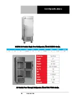
Страница 10: ...10 888 994 7636 Unit Specifications 2127AC Air Curtain Single Door Refrigerator Model 2127AC shown Air Curtain Pass Through Refrigerator Model TAS PTAC shown ...

Страница 11: ...ck that the condenser and evaporator fans rotate freely without striking any stationary members 3 Unit must be properly leveled check all legs or casters to ensure they all are in contact with the floor while maintaining a level work surface Adjusting bullet feet heights or shimming casters may be necessary if the floor is not level NOTE Damage to equipment may result if not followed Randell is no...

Страница 12: ...ated inside the mechanical housing NOTE It is important that a voltage reading be made at the compressor motor electrical connections while the unit is in operation to verify the correct voltage required by the compressor is being supplied Low or high voltage can detrimentally affect operation and thereby void its warranty NOTE it is important that your unit has its own dedicated line Condensing u...

Страница 13: ... unit is capable of maintaining 40 F or below at 100 F ambient with the door closed When loading product in the cabinet allow enough space for proper air flow circulation When operating with the door open keep install trays on all the shelf brackets and pushed in all the way to prevent disruption of the air flow Open the door completely and latch to the side of the cabinet body while loading and u...

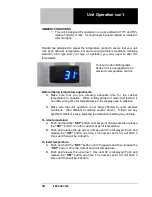
Страница 14: ...is not being effected by room ambient conditions See Ambient Conditions section above If there are any significant ambient issues adjusting the temperature setting may not help To raise temperature A Push and hold the SET button until set point 33 appears then release the SET button 33 is the current set point temperature B Push and release the up arrow 2 times until 35 is displayed Push and relea...

Страница 15: ... F F CF rE Resolution 0 0 C only C in rE Ld Probe Displayed P1 or P2 P1 Ld dy Display Temperature Delay 0 dy dE Defrost Termination Temp 42 dE Id Interval between Defrosts 8 Id nd Maximum length of Defrost 25 nd dF Display during Defrost it dF AU Alarm Upper max alarm 70 AU AL Alarm Lower minimum alarm 25 AL Ad Alarm Delay min 60 Ad dA Alarm Delay at startup hrs 10min 60 dA d2 Evaporator probe dis...

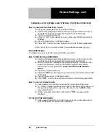
Страница 16: ...r 3 seconds the defrost and water drops symbol will start blinking 2 When a parameter is displayed keep pressed the Set down arrows for more than 7 seconds The Pr2 label will be displayed immediately followed from the HY parameter NOW YOU ARE IN THE HIDDEN MENU 3 Select the required parameter 4 Press the SET key to display its value Now only the defrost symbol LED is blinking 5 Use up or down arro...

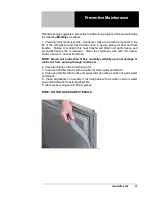
Страница 17: ...he compressor Clean the condenser coils with coil cleaner and or a vacuum cleaner and brush NOTE Brush coil in direction of fins normally vertically as to not damage or restrict air from passing through condenser 2 Clean fan blade on the condensing unit 3 Clean and disinfect drains with a solution of warm water and bleach 4 Clean and disinfect drain lines and evaporator pan with a solution of warm...

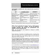
Страница 18: ... wash equipment as damage to electrical components may result Proper maintenance of equipment is the ultimate necessity in preventing costly repairs By evaluating each unit on a regular schedule you can often catch and repair minor problems before they completely disable the unit and become burdensome on your entire operation For more information on preventive maintenance consult your local servic...

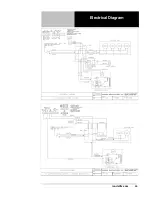
Страница 19: ...randellfx com 19 Electrical Diagram ...

Страница 20: ...ad repeatedly tripping 4 Check outlet voltage Unit runs constantly 1 Condenser coil dirty 1 Clean coil 2 Condenser fan faulty 2 Service condenser motor 3 Room ambient too high 3 Reduce room temp to 75F 4 Room humidity too high 4 Set room lower Unit not cold enough 1 Temp control set too high 1 Adjust control to lower setting 2 Temperature control faulty 2 Test control 3 Condenser coil dirty 3 Clea...

Страница 21: ...randellfx com 21 Replacement Parts Call factory for replacement parts 800 621 8560 Randell Service and Parts Hotline ...

Страница 22: ...22 888 994 7636 Replacement Parts cont ...

Страница 23: ...randellfx com 23 NOTES ...

Отзывы: