background image

Technical features and dimensions

7

2.1 - TECHNICAL FEATURES

The XC-K boilers are made up of an external shell which houses
the completely wet blind cylindrical furnace, where the first
two combustion gas passes are completed, and by a special
tube and shell, used for the third pass.

The tube and shell, placed horizontally in the lower part of the
body, is composed of stainless steel 316L tubes and aluminium
fins.

The guided path of the combustion gas exploits the thermal
exchange surfaces to a maximum and evenly balances strains
on the materials.
The construction fully complies with prescriptions laid down in
EN 303 part 1.
The components of the pressurised part, such as sheets and
tubes, are made in certified carbon steel, according to the
EURONORM 25 and EURONORM 28 tables.
Welding devices and procedures are approved by TÜV (D) -
UDT (PL) - SA (S) and ISPESL (I).
The boilers are equipped with an opening door on the right or left.
The outer shell is covered with a glass wool  insulation 100 mm
thick, in turn protected by a mineral fibre fabric.
The top part of the shell is provided with hooks for lifting the
boiler.

Note: XC-K boilers are designed to operate with ON/OFF, dual
stage or modulating burner, as long as the minimum heat output
that can be reached is no lower than the value indicated on the
technical data plate.

The boilers are provided with two ½” attachments for conduits
with an inside diameter of 15 mm (suitable to house 3 bulbs

each).
The shell has holes at the sides for the cable glands of the
power, pumps, burner cables and those of any other auxiliary
device.

2

TECHNICAL FEATURES
AND DIMENSIONS

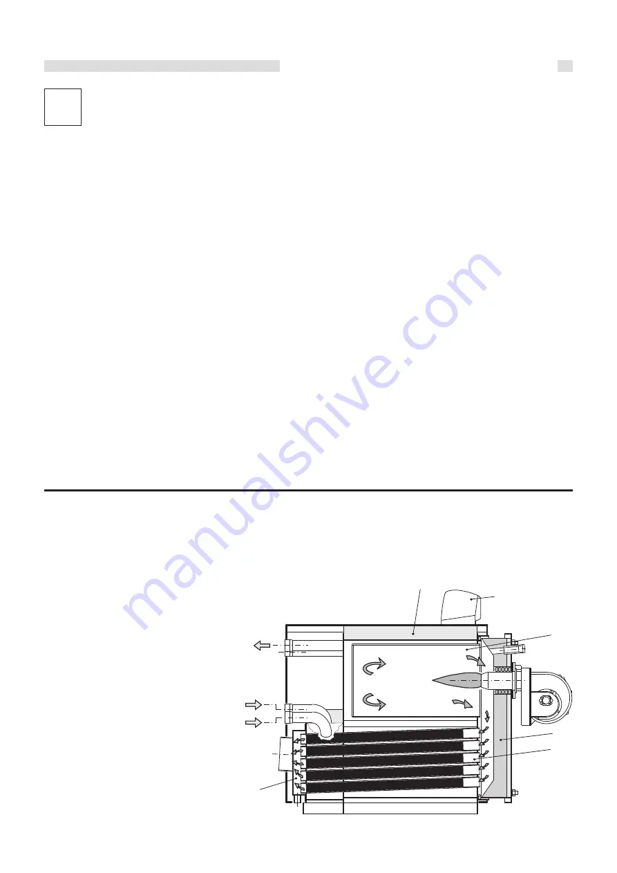
2.2 - MAIN COMPONENTS

XC-K boilers are equipped with a blind cylindrical furnace, in
which the central flame of the burner is reversed peripherally
towards the front. When the combustion gases have reached
the front part, they are sent through the door into the tubes of
the third pass to reach the rear flue gas chamber and then the
chimney.
The combustion chamber is always pressurised while the burner
is operating, within the power range of the boiler.
For the value of this pressure, see the tables
on pages 8÷10, in the column “Flue gas side
pressure drops”.
The chimney must be calculated so that
no positive pressure is detected
at its base.

1

Furnace

2

Smoke pipes with smoke diverters

3

Door with flame sight glass

4

Smoke chamber

5

Body insulation

6

Panel board

M Flow
Rbt  Low temperature return
Rat  High temperature return

fig. 1

1

2

3

6

5

4

M

Rat

Rbt

Содержание XC-K Series

Страница 1: ...INSTALLATION AND MAINTENANCE INSTRUCTIONS 44879 03 12 rev 0 XC K...

Страница 2: ...12 Connecting gas 20 3 13 Packaging 21 3 14 Assembling casing 22 3 15 Electrical connections 24 3 16 MODULATING MASTER panel board code 37892 26 3 17 Programming heating controllers with single boiler...

Страница 3: ...occasion also check the state of wear of the anode 1 4 INFORMATION FOR SYSTEM MANAGER The user must be instructed concerning the use and operation of his heating system in particular Deliver these in...

Страница 4: ...rts which affect the operating safety of the appliance Attention To tighten or loosen the screwed fittings use only appropriate fixed spanners Incompliant use and or inappropriate tools can cause dama...

Страница 5: ...the document case it must be applied by the installer on the outside of the casing The serial number of the boiler is on the riveted plaque on the front plate of the body front right bottom side Cond...

Страница 6: ...ot try to repair it or intervene on it directly Contact only personnel qualified in compliance with law Any repairs must be performed solely by personnel authorised by Unical using original spare part...

Страница 7: ...re designed to operate with ON OFF dual stage or modulating burner as long as the minimum heat output that can be reached is no lower than the value indicated on the technical data plate The boilers a...

Страница 8: ...140 Pressure drop water side kPa 1 5 9 8 Pressure drop flue side daPa Maximum operating pressure boiler bar 6 Weight kg 365 Minimum dimensions for boiler room access Pressure drops corresponding to a...

Страница 9: ...rop water side kPa 3 8 2 5 3 2 2 2 9 18 6 25 4 32 3 34 3 39 2 Pressure drop flue side daPa Maximum operating pressure boiler bar 6 6 6 6 6 Weight kg 525 660 800 1007 1137 XC K 200 570 fig 4 200 290 40...

Страница 10: ...8 1983 CONNECTIONS T1 T2 UNI 2276 PN6 T4 UNI 2276 PN6 T5 ISO 7 1 T6 mm DN 125 DN 125 DN 150 DN 150 DN 200 DN 200 DN 125 DN 125 DN 150 DN 150 DN 200 DN 200 DN 65 DN 65 DN 80 DN 80 DN 100 DN 100 Rp 1 R...

Страница 11: ...0 60 C Nominal heat output 50 30 C Nominal heat input Heat efficiency at nominal load 80 60 C Heat efficiency at nominal load 50 30 C Heat efficiency at 30 load Combustion efficiency 80 60 C Combustio...

Страница 12: ...b Check that boiler is set up to operate with the available type of fuel This can be seen written on the package and on the technical feature plate c Check that the chimney flue has an appropriate dr...

Страница 13: ...cable technical standards XC K is a steel boiler which can be combined with air blown burners operating on gas of category II2H3 Contact the gas supplying company before installing the appliance Direc...

Страница 14: ...hooks or shifting it on rollers underneath the sturdy base longerons 3 5 BURNER The burners operating with the XC K boilers must have the EC certification and comply with Gas appliance directive 90 39...

Страница 15: ...ep it from blackening If the cooling tube is not connected to the sight glass it could break ATTENTION the flame sight glass can be very hot therefore pay the utmost attention fig 13 3 5 2 INSTALLING...

Страница 16: ...B Crosswise rotation loosening the hinges fixed on the front plate of the boiler and moving them sideways C Axial rotation screwing different tightening nuts fig 14 3 7 2 XC K 1140 XC K 1420 BOILERS F...

Страница 17: ...ollowing adjustments can be made on the door of these boiler models A Vertical adjustment by acting on the nut of the upper hinge pin which the door turns on B Crosswise rotation loosening the hinges...

Страница 18: ...for the evacuation of combustion products which must be filled after assembly and must remain at least 25 mm high with the boiler running see fig 17 Do not discharge condensation through gutter drainp...

Страница 19: ...s precaution is not taken triggering of the safety valve can cause damage to persons animals and objects for which the manufacturer cannot be held responsible Connection of expansion vessel XC K boile...

Страница 20: ...n system and therefore before connecting it to the gas meter check its sealing carefully If any part of the system is out of sight the sealing test must be done before the pipes are covered Before con...

Страница 21: ...astic bags etc must be kept out of the reach of children as they are potential sources of danger Unical will not be held liable for damage to persons animals or objects due to failure to comply with t...

Страница 22: ...having greased the relevant part with the specific solvent The plates are included in the document envelope Assembly sequence Ref fig 18 21 A Mount the insulation jackets pos 1 and 2 of the boiler bo...

Страница 23: ...nd insert the electric inlet cables and the outlet probe capillaries through the slots at the base Fit the panel board to the upper panel pos 9 Fit the upper panel pos 9 complete with panel board to t...

Страница 24: ...electric inlet cables and the outlet probe capillaries through the slots at the base Fit the panel board to the upper panel pos 13 Fit the upper panel pos 13 complete with panel board to the two side...

Страница 25: ...wet and or moist parts of the body and or in bare feet do not pull the electric cables do not leave the appliance exposed to atmospheric agents rain sun etc unless expressly designed do not allow chi...

Страница 26: ...e system pump switch 21 Pz2 mixed zone system pump switch 33Working thermostat 35Safety thermostat The heating controller probes boiler storage tank external flow are included in the supply the ambien...

Страница 27: ...110 C MAX T HS2 85 C 01 08 BOILER BUS ID 10 C 80 C MIN T HS2 10 C 0 11 VOLTAGE CURVE 11 0 00 10 00V CURVE 11 U2 0V 0 00 10 00V CURVE 11 U2 10V 00 120 C CURVE 11 T1 0 C 00 120 C CURVE 11 T2 100 C 0 00...

Страница 28: ...ault Individual values Value range Description DOMESTIC HOT WATER PRODUCTION 00 01 OFF ON CHARGE PUMP 01 ON 00 01 02 03 PARALLEL PUMP RUNNING 01 00K 50K T DHW 20K 5K 30K DHW HYSTERESIS 5 degrees 00 mi...

Страница 29: ...1 02 00 03 MF 1 4 T NOM 30 C 5 25 MF 1 4 HYSTERESIS 5 C 5 25 F 15 FUNCTION 0 Exit level using RETURN C OK 1 2 1 2 1s C C C BUS ID 1 2 11 Mod Run 2 1 PARAMETERS PROGRAMMABLE BY TECHNICIAN FOR HEATING C...

Страница 30: ...domestic hot water production Key M flow Rat HIGH temperature return Rbt LOW temperature return Vmix2 zone mixer valve motorised Pz1 HIGH TEMPERATURE zone heating system pump Pz2 LOW TEMPERATURE zone...

Страница 31: ...pump for DHW production switches on automatically and will only switch off when the temperature set on the heating controller has been reached The panel is set up to manage the modulating burners Wit...

Страница 32: ...TED BY ACCESS CODE FOR HEATING CONTROLLER type E8 5064 00 01 OFF ON TEMPERATURE MASTER 30 C 110 C MAX T HS1 MAX T HEADER 10 C 80 C MIN T HS1 MIN T HEADER 01 ON 85 C 10 C 0 01 BUS CONNECTION 01 00 01 O...

Страница 33: ...1 in the second leave dashes Set value of first stage of second boiler at 1 in the second leave dashes If there are more than 2 boilers in cascade enable the first stages of the boilers in cascade See...

Страница 34: ...ED MAX FLOW TEMPERATURE MIN FLOW TEMPERATURE FROST PROTECTION TEMP OUTSIDE TEMP DELAY HEATING SLOPE DISTANCE B HEAT SINK Exit level using RETURN Default Individual values Value range Description SOLAR...

Страница 35: ...2 Press OK 2 3 Turn the knob 3 until mm appears on the display 4 Press OK 2 2 1 Switch the selector 1 to the symbol of the mixer valve 2 Press OK 2 3 Turn the knob 3 until the number 15 appears on the...

Страница 36: ...working temperature of the boiler n 2 is regulated by the heating controller to achieve this the thermostat must be placed at maximum full scale pos 32 Modulation of the burner will be managed by heat...

Страница 37: ...2 Press OK 2 3 Turn the knob 3 until mm appears on the display 4 Press OK 2 2 1 Switch the selector 1 to the symbol of the mixer valve 2 Press OK 2 3 Turn the knob 3 until the number 15 appears on the...

Страница 38: ...ion fig 28 Ps DHW recirculation pump P1 circulation pump Pb DHW production charge pump SPF storage tank probe KF E8 5064 heat control boiler probe KF 1 Lago Basic 0201 RV 1 heat control boiler probe V...

Страница 39: ...e storage tank charge pump for DHW production switches on automatically and will only switch off when the temperature set on the heating controller has been reached The panel is set up to manage the m...

Страница 40: ...system pump switch 21 Pz2 mixed zone system pump switch 33Working thermostat 35Safety thermostat The heating controller probes boiler storage tank external flow are included in the supply the ambient...

Страница 41: ...ODULATION CASCADE DHW LEVELS CONTROL VARIANCE DISPLAY NOMINAL OUTPUT INDEX DISPLAY SWITCH VALUE DISPLAY REMAINING min BLOCK TIME DISPLAY MAXIMUM BOILER TEMPERATURE BOILER DYNAMICS UPWARD BOILER DYNAMI...

Страница 42: ...YSTERESIS 5 degrees DHW FOLLOWUP THERMOSTAT INPUT THERMOSTAT FUNCTIONING Exit level using RETURN LOAD THROUGH Default Individual values Value range Description HEATING CIRCUIT 1 HEATING CIRCUIT FUNCTI...

Страница 43: ...PARAMETERS PROGRAMMABLE BY TECHNICIAN FOR HEATING CONTROLLER Lago Basic 0201 RV 1 1 2 3 1 1 Switch selector to burner 1 2 Press OK 2 3 Turn the knob 3 until 2 appears on the display dual stage burner...

Страница 44: ...zone 1 low temperature zone controlled by a motorised mixer valve domestic hot water production Key Vmix2 zone mixer valve motorised Pz1 HIGH TEMPERATURE zone heating system pump Pz2 LOW TEMPERATURE z...

Страница 45: ...pump for DHW production switches on automatically and will only switch off when the temperature set on the heating controller has been reached The panel is set up to manage the modulating burners With...

Страница 46: ...T HS1 MAX T HEADER MIN T HS1 MIN T HEADER BUS CONNECTION BUS SUPPLY HYSTERESIS HYSTERESIS TIME MINIMUM LIMIT MAX T HS2 BOILER BUS ID MIN T HS2 VOLTAGE CURVE CURVE 11 U2 CURVE 11 U2 CURVE 11 T1 CURVE...

Страница 47: ...ble the first and second stages of the boilers in cascade See E8 5064 heating controller instruction book Default Individual values Value range Description DOMESTIC HOT WATER PRODUCTION CHARGE PUMP PA...

Страница 48: ...ED MAX FLOW TEMPERATURE MIN FLOW TEMPERATURE FROST PROTECTION TEMP OUTSIDE TEMP DELAY HEATING SLOPE DISTANCE B HEAT SINK Exit level using RETURN Default Individual values Value range Description SOLAR...

Страница 49: ...2 Press OK 2 3 Turn the knob 3 until mm appears on the display 4 Press OK 2 2 1 Switch the selector 1 to the symbol of the mixer valve 2 Press OK 2 3 Turn the knob 3 until the number 15 appears on the...

Страница 50: ...working temperature of the boiler n 2 is regulated by the heating controller to achieve this the thermostat must be placed at maximum full scale pos 32 Modulation of the burner will be managed by heat...

Страница 51: ...1 2 Press OK 2 3 Turn the knob 3 until 2 appears on the display dual stage burner 4 Press OK 2 2 1 Switch the selector 1 to the symbol of the mixer valve 2 Press OK 2 3 Turn the knob 3 until the numb...

Страница 52: ...ystem consisting in 2 boilers in cascade serving 1 high temperature zone 1 low temperature zone controlled by a motorised mixer valve domestic hot water production Boiler n 1 is fitted with a panel bo...

Страница 53: ...e storage tank charge pump for DHW production switches on automatically and will only switch off when the temperature set on the heating controller has been reached The panel is set up to manage the m...

Страница 54: ...RATING INSTRUCTIONS Information for system manager The system manager must be instructed concerning the use and operation of his heating system in particular Give the system manager the SYSTEM MANAGER...

Страница 55: ...enance is required to eliminate any differences between the actual status and the nominal status This is normally done by cleaning setting and replacing individual components subject to wear Maintenan...

Страница 56: ...w signs of deterioration if so they must be replaced using only original spare parts Maintenance of burner Burner maintenance must be carried out by personnel authorised by its manufacturer or else th...

Страница 57: ...Inspections and maintenance 57...

Страница 58: ...58 Inspections and maintenance...

Страница 59: ...Inspections and maintenance 59...

Страница 60: ...www unical eu info unical ag com Unical will not be held responsible for possible inaccuracies if due to transcription or printing errors It also reserves the right to modify its products as deemed n...

Отзывы: