SECTION 7
42
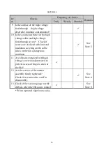
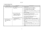
Trouble symptom
Possible cause
Corrective action
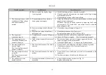
B. Short-circuit of the high voltage
lines to ground.
a. Check if the filament line is shorted to ground.
b. Check if particles of evaporant are caught on the high voltage
feed-through terminals.
c. Check the high voltage cable for insulation.
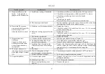
3. The beam spot is not visible
in the hearth. High voltage
and beam current are
normal.
A. Poor adjustment of the electron
beam gun power supply.
a. Adjust the deflection coil current in accordance with the power
supply instruction manual.
The beam spot can be nearly centered by adjust-ing the X-axis
coil current to 1.75A and the Y-axis current to zero when the
high voltage is 10 kV.
B. Incorrect wiring of the deflection
coils.
a. Check the wiring referring to Figure 3.4.
C. Layer short or short of the X-axis
deflection coil.
a. Check the resistance of the X-axis coil.
The normal resistance is 2.8 10% at 20 C.
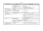
4. The beam spot
sometimes moves.
A. Unstable focus current of EB power
supply.
a. Check the deflection coil lead for contact and insulation.
b. Failure of E/B power supply (See its instruction manual.)
5. The beam spot moves
toward the filament with
increase of power.
A. High voltage drops with increase of
power.
a. The electron beam gun power supply appears defective. See
the power supply instruction manual.
b. Check the 3-phase input voltage to see if phase is open.
6. The magnet indicator
does not light.
The X-axis deflection coil
current is normal.
A. The X-axis deflection coil or lead is
shorted.
a. Check if the X-axis deflection coil lead is shorted to ground.
b. Check the resistance of the X-axis deflection coil.
( 2.8 10% at 20 C )
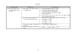
7. The magnet indicator does
not light.
The X-axis focus current
does not flow.
A. The X-axis deflection coil or lead is
broken.
a. Check if the X-axis deflection coil lead is disconnected at the
connection.
b. Check the resistance of the X-axis deflection coil.
8. The anode plate is red
heated or melts.
A. Incorrect dimensions of the emitter
assembly.
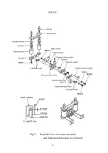
a. Correct the dimensions as shown in Fig. 5.1.
Replace deformed parts.
Содержание EGL-206M
Страница 2: ...EB0007 03e...
Страница 3: ...EB0007 03e...
Страница 10: ......
Страница 13: ...SECTION 1 3 Fig 1 1 Dimensional Drawing for EGL 206M EGL 406M...
Страница 24: ...SECTION 3 14 Fig 3 1 Installation of two or more electron beam guns...
Страница 26: ...SECTION 3 16 Fig 3 3 Typical water cooling piping arrangement...
Страница 27: ...SECTION 3 17 Fig 3 4 Wiring arrangement in vacuum chamber...
Страница 28: ...SECTION 3 18 VIEW PORT LEADEN GLASS X RAY SUS304 SHIELD GASKET BELLJAR TARGET Fig 3 5 X ray shield...
Страница 38: ...SECTION 5 28 Fig 5 1 Exploded view of emitter assembly and dimensional drawing for electrode...
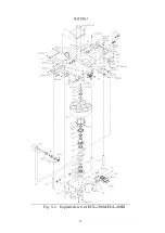
Страница 42: ...SECTION 5 32 Fig 5 2 Exploded view of EGL 206M EGL 406M...
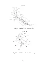
Страница 43: ...SECTION 5 33 Fig 5 3 Exploded view of emitter assembly Fig 5 4 Exploded view of Limit switch assembly...

