SECTION 3
9
NOTE
The ferromagnet is more than 100 mm away from the electron beam gun. If
there is a magnetic device such as an ion pump nearby, make sure that the
magnetic flux density at the electron beam gun installation position is 1 Gauss
or less.
CAUTION
If a hearth of EGL-206M/EGL-406M is operated by a motor drive, take care
so that hand is not caught in the device.
(3)
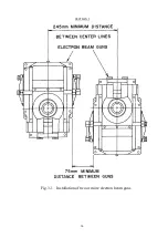
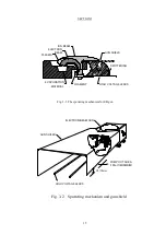
Installing multiple EG guns (See Fig. 3.1.)
Magnetic interference will occur if two or more EB guns are installed in
proximity to each other. To prevent this, provide a space of more than 75
mm between the sides of EB guns when the filament is mounted in the
opposite direction. Also provide a space of more than 130 mm between the
sides of the EB guns when the filament is mounted in the same direction.
Even if these actions are taken, the beam spot may be deformed slightly or the
beam may not be deflected over the entire surface of the crucible.
(4)
High voltage feed-through
In installing the H.V. feedthrough, avoid a location that provides easy access
to operator
’
s hand. Cover the electrode on the atmosphere side with a rigid
metal cover.
DANGER
The cover must be a sealed one that does not allow access of fingers, sticks or
the like.
(5)
Filament cable
Use a single or multi-core copper cable having a cross section of 10 mm
2
or
more. Make wiring arrangement so that the distance between the filament
terminal of the electron beam gun and that the terminals of the high voltage
feedthrough is as short as possible and the gun shield (mentioned in the
latter part of this manual) can be easily set. The recommended wire
thickness is 4 mm in diameter if the cable length is around 20 cm, and 5 mm
Содержание EGL-206M
Страница 2: ...EB0007 03e...
Страница 3: ...EB0007 03e...
Страница 10: ......
Страница 13: ...SECTION 1 3 Fig 1 1 Dimensional Drawing for EGL 206M EGL 406M...
Страница 24: ...SECTION 3 14 Fig 3 1 Installation of two or more electron beam guns...
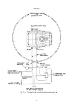
Страница 26: ...SECTION 3 16 Fig 3 3 Typical water cooling piping arrangement...
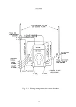
Страница 27: ...SECTION 3 17 Fig 3 4 Wiring arrangement in vacuum chamber...
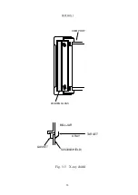
Страница 28: ...SECTION 3 18 VIEW PORT LEADEN GLASS X RAY SUS304 SHIELD GASKET BELLJAR TARGET Fig 3 5 X ray shield...
Страница 38: ...SECTION 5 28 Fig 5 1 Exploded view of emitter assembly and dimensional drawing for electrode...
Страница 42: ...SECTION 5 32 Fig 5 2 Exploded view of EGL 206M EGL 406M...
Страница 43: ...SECTION 5 33 Fig 5 3 Exploded view of emitter assembly Fig 5 4 Exploded view of Limit switch assembly...


