SECTION 5
29
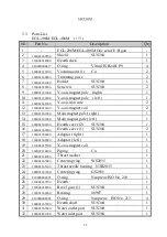
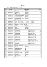
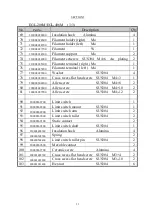
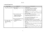
5.3 Parts List
EGL-206M/EGL-406M ( 1/3 )
No.
Part No.
Description
Q
’
ty
1
-
EGL-206M/EGL-406M One set of E/B gun
-
2
200001660700
Shield
SUS304
1
3
210004014000
Hearth deck
1
4
C10000000417
O-ring
Viton JIS B2401 P9
4
5
200001615100
Vacuum joint (1)
Cu
2
6
200001660900
Trimming piece
2
7
200001661000
Holder
SUS304
1
8
210004030200
Setscrew
SUS304
2
9
200001661200
Y-axis magnet pole (right)
1
10
200001661400
Y-axis magnet pole ( left )
1
11
200001661600
Y-axis iron core
2
12
210004016100
Y-axis magnet coil
2
13
200001661800
Main magnet pole ( right )
1
14
200001662000
Main magnet pole ( left )
1
15
200001662100
Hearth cover (2)
SUS304
1
16
200001662200
Hearth cover (1)
SUS304
2
17
200001662400
Adaptor ( right )
1
18
200001662600
Adaptor ( left )
1
19
210004015500
X-axis magnet coil
1
20
200007218400
Piping
Cu
1
21
200001662900
Thrust washer
1
22
200001663000
Centering ring WS2035
1
23
200001663100
Thrust needle bearing NTB2035
1
24
200001663200
Centering ring
GS2035
1
25
C10000000001
O-ring
Neoprene ISO No. 210
1
26
210004039700
Hearth
1
27
210004030300
Bevel gear (1)
SUS304
1
28
200001663400
Bearing
#6907
1
29
C10000000002
O-ring
Neoprene ISO No. 213
4
30
200001663500
Hearth shaft
SUS304
1
31
200001663600
Water outlet port SUS304
1
32
200001663700
Water inlet port
SUS304
1
Содержание EGL-206M
Страница 2: ...EB0007 03e...
Страница 3: ...EB0007 03e...
Страница 10: ......
Страница 13: ...SECTION 1 3 Fig 1 1 Dimensional Drawing for EGL 206M EGL 406M...
Страница 24: ...SECTION 3 14 Fig 3 1 Installation of two or more electron beam guns...
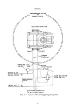
Страница 26: ...SECTION 3 16 Fig 3 3 Typical water cooling piping arrangement...
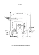
Страница 27: ...SECTION 3 17 Fig 3 4 Wiring arrangement in vacuum chamber...
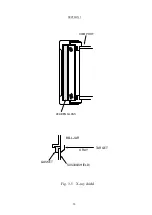
Страница 28: ...SECTION 3 18 VIEW PORT LEADEN GLASS X RAY SUS304 SHIELD GASKET BELLJAR TARGET Fig 3 5 X ray shield...
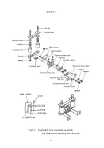
Страница 38: ...SECTION 5 28 Fig 5 1 Exploded view of emitter assembly and dimensional drawing for electrode...
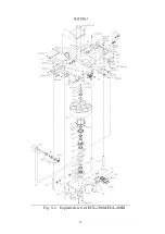
Страница 42: ...SECTION 5 32 Fig 5 2 Exploded view of EGL 206M EGL 406M...
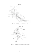
Страница 43: ...SECTION 5 33 Fig 5 3 Exploded view of emitter assembly Fig 5 4 Exploded view of Limit switch assembly...

