19-2021 Rev E, 06/05/07
8
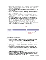
20. After installation of the last Lamp Module on the side opposite of the Power Junction
Module, route the power wires from the last Lamp Module installed through the feed
through hole connecting the wire raceway from either side.
Do not install lamps at this
stage. (see Figure 3c for example of completely wired system)
Figure 3c
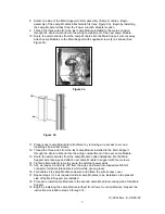
INSTALLATION OF THE POWER JUNCTION MODULE
Figure 4a
21. Remove Power Junction Module cover.
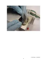
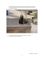
22. Thread wires from last Lamp Module installed on each side through Power Junction
Module strain relief (See Figure 4a).
23. Attach Power Junction Module to support with screws provided (2) as shown in
Figure 4a.
24. Pull wires through strain relief until slack is removed and tighten strain relief screws
to secure the wires entering the Power Junction Module
25. Cut and strip wires, 3/8", and insert into respective WAGO connector terminals
(black-black, white-white, green-green), as required.
26. Fold cables into Power Junction Module enclosure.
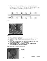
PREPARATION OF THE WIRE/RACEWAY COVER
Raceway
Содержание High Output UV Device V-Flex
Страница 11: ...19 2021 Rev E 06 05 07 11...

