background image


19-2021 Rev E, 06/05/07 

10 

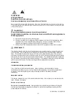
ELECTRICAL CONNECTION OF THE SYSTEM 
 

  WARNING 

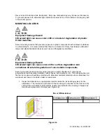
Personal Serious Injury Hazard 
Power supply can cause severe electrical shock. 

 
Disconnect power supply before installation.  All wiring should be in accordance with NEC.  
 

1.  Bring power to the Power Junction Module and use appropriate knock-out on the 

Power Junction Module. 

2.  Install power conduit connector. 
3.  Using supplied WAGO connector terminals, connect assembly wires to power supply.  

(Line in to black, neutral to white, and earth ground to green).  

4.  Attach the Power Junction Module cover with two nuts.  


WARNING 

UV Light Hazard 
Harmful to bare skin and eyes. 
Can cause temporary or permanent loss of vision. 

 
Never look at the lamps while illuminated.  Only view illumination by way of view port accessory.  
To prevent exposure to ultraviolet light, disconnect power to the V-Flex

T M

 before servicing any 

part of the HVAC system. 


WARNING 


The electrical supply circuit connected to this UV appliance must be routed through an electrical 
interlock switch placed on the HVAC system duct access panels and doors to prevent accidental 
UV exposure when servicing the air ducts or equipment.  


LAMP INSTALLATION 


CAUTION


Breakable Glass Hazard 
Can cause personal injury.


Be careful when inserting lamp into lamp base.  Wear protective gloves when handling lamp. 
 

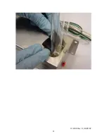
1.  To install lamps into Lamp Modules.  Slide lamp  and black clip into the lamp module 

as shown in the below picture: 


Содержание High Output UV Device V-Flex

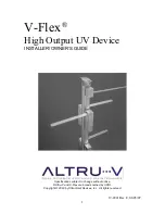
Страница 1: ...05 07 1 V Flex High Output UV Device INSTALLER OWNER S GUIDE Specifications subject to change without notice Altru V and V Flex are brands owned by UVDI Copyright 2003 by UltraViolet Devices Inc All...

Страница 2: ...ING LOCATION 5 INSTALLATION OF THE LAMP MODULES 6 INSTALLATION OF THE POWER JUNCTION MODULE 8 INSTALLATION OF MAIN SUPPORT INTO AIR HANDLING DUCT 9 ELECTRICAL CONNECTION OF THE SYSTEM 10 LAMP INSTALLA...

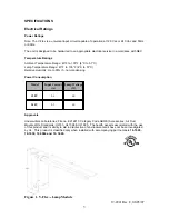
Страница 3: ...to 135 F 4 C to 51 C Relative Humidity Up to 95 rh non condensing Power Consumption Model Input Current A Lamp Wattage W 120V 0 6 60 240V 0 3 60 Approvals Underwriters Laboratories File no E212213 Ca...

Страница 4: ...switches must be installed at any access panel or door within view of the UV fixtures 4 The installer must be a trained experienced service technician 5 After installation is complete check out produc...

Страница 5: ...pment Damage Hazard Ultraviolet light can cause color shift or surface degradation and sometimes structural degradation of non metallic components Select a mounting location that prevents exposure to...

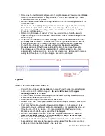
Страница 6: ...ction of the Main Support using a tool appropriate for cutting aluminum Cut only from one end as it is important to retain a wiring feed through hole in the Main Support section to be installed Figure...

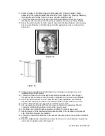
Страница 7: ...wires from the last Lamp Module installed to the Main Support through the strain relief and into the wiring compartment of the next Lamp Module 13 Route the external wires from the Lamp Module under...

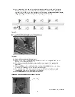
Страница 8: ...ove Power Junction Module cover 22 Thread wires from last Lamp Module installed on each side through Power Junction Module strain relief See Figure 4a 23 Attach Power Junction Module to support with s...

Страница 9: ...ain Support for all gaps existing in the Main Support raceway INSTALLATION OF MAIN SUPPORT INTO AIR HANDLING DUCT 1 Carefully carry the partially assembled Main Support into the installation area 2 Pl...

Страница 10: ...skin and eyes Can cause temporary or permanent loss of vision Never look at the lamps while illuminated Only view illumination by way of view port accessory To prevent exposure to ultraviolet light d...

Страница 11: ...19 2021 Rev E 06 05 07 11...

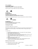
Страница 12: ...module so that is holding the lamp in place and the clip is secured onto the metal module Make sure the clip is slid over the lamp module as shown below 3 Push the lamp in till it snaps into place Ver...

Страница 13: ...ook directly into the duct to see the illuminated ultraviolet lamp The installer should orient the owner to the unit by demonstrating use of the view port accessory and discussing how to determine whe...

Страница 14: ...ry If the air stream is filtered cleaning schedule may be reduced To clean the lamp 1 Disconnect power to HVAC system Never enter system with UV lamps illuminated 2 Open the system access panel or doo...

Страница 15: ...ert new lamp into the Lamp Module Depress lamp release button and insert lamp Let go of the lamp release button and verify that lamp is retained 6 Reconnect the power to the HVAC system 7 Clean the la...

Страница 16: ...NT EXCEED THE COST OF THE GOODS SOLD UNDER THIS CONTRACT OF SALE UVDI neither assumes nor authorizes any person to assume for it any obligation in connection with the goods This warranty shall not app...

Отзывы: