background image

5

1.  INTRODUCTION AND ASSEMBLY

1.1  Ultrasound humidifier

UltraSonic humidifiers can be used for a variety of applications, e.g. 

data centers, humidors, process machines, wine rooms, music rooms to 

maintain a given RH% control. Either UP01 or UP02 compact humidifer 

can be used as a self standing unit with a distributer attached to the 

top of each cabinet or used with a plastic hose to distrubute mist into 

a stainless steel  wand that has approx. 30 small holes to allow mist to 

evenly distribute mist. Caution: stainless steel wand must be sloped back 

to humidifer to drain any mist that may have condensed in tube or wand. 

Mist dispacement is 1.1 lb/hr using Ultra Pure (UP01) cabinet and 2.2lb.

hr using Ultra Pure (UP02), delivered directly into the air stream running 

100% for 1 hour.

1.2  Dimensions and weights

1 lbs/hr  and 2 lbs/hr

   (UP01 and UP02)    


Fig. 1.a

UP01

UP02

dim. inches

A  Depth

9"

9"

B  Width

12"

12"

C Height

11"

11"

weights ((lb)

packaged

40 Pounds

46 Pounds

empty

36 Pounds 

39 Pounds 

Tab. 1.a 

1.3  Opening the packaging 

• 

Make sure the humidifier is intact upon delivery and immediately 

notate on BOL any damage to box or glass sticker affixed to each 

box. Notify Ultra Pure immediately due to careless or improper 

transport. 

• 

Move the humidifier to the site of installation before removing from 

the packaging 

• 

Open the cardboard box, remove the protective material and 

remove the humidifier

• 

The following are contained inside  (fig 1): 

• 

A: IOM manual

• 

B: Optional accessories if purchased ie, distributor, 50M filter, 

plastic tube seperate box, S/S distributer seperate box 

• 

10'  1/4" RED inlet water & 3/8" BLACK drain hose 

1.4  Positioning  

Ultra Pure has taken every measure to provide a self contained humidifer 

for ease of installation and startup. 

In order to produce even mist across the water bed inside humidifer 

make sure cabinet is on a level surface. In order to set onto a flat surface 

(1)  2” hole will need to be drilled to allow for drain line to not impead 

with cabinet setting flat on surface. Installing drain is required and will 

void warranty if not terminated and ran to an approved drain. 

Both cabinets can also be hung onto a wall. In order to have accces to the 

humidifier deep or shallow channel strut is required to secure cabinet 

prior to hanging onto wall. 

Confirm cabinet is level on wall front to back and side to side. 

Temperature and Humidity conditions that change throughout day will 

also change the distance of absorption. Please allow for 60” clear space in 

front f humidifier or optional S/S wand. 

1.5  Fastening

Fastening instructions:

1. 

Fastening instructions:

2. 

Use (4) spring nuts and 3/8” bolts to attach to unistrut Fig. 1.b;

3. 

Confirm that humidifer mist leaving cabinet does not have any 

obstructions close to or the possibiility that mist can touch anything 

prior to being absorbed into air stream. 

4. 


 FLOOR

WALL

CEILING

Humidifier

60.0” min required clearance 

24.0” min required clearance 

60.0” min 

required clearance

-No obstructions-

Fig. 1.b

Fig. 1.c

Содержание pureMist

Страница 1: ...NO POWER SIGNAL CABLES TOGETHER READ CAREFULLY IN THE TEXT Engineering Manual Compact Ultrasonic Humidifier...

Страница 2: ...r with the characteristics indicated in this manual must be used for water vapor production Alloperationsontheproductmustbecarriedoutaccordingtotheinstructions provided in this manual and on the label...

Страница 3: ...2 Meaning of the symbols 12 6 3 Keypad 12 6 4 Main display 12 6 5 Display software release 12 7 CONFIGURATION PARAMETERS 13 7 1 Basic parameters 13 7 2 Advanced parameters 13 8 ALARMS 14 9 MAINTENANC...

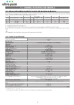
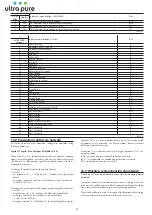
Страница 4: ...essories Wand Distributor Production Supply Temperature Electrical Rating Amp Max Weight Dimensions 1 1 2 2 Lbs Hr 33 8 104 F 115 V 60Hz 8 MFS 15 28lbs 12 x 9 x 11 Temp Hum Stat Diffuser Remote Displa...

Страница 5: ...fier The following are contained inside fig 1 A IOM manual B Optional accessories if purchased ie distributor 50M filter plastic tube seperate box S S distributer seperate box 10 1 4 RED inlet water 3...

Страница 6: ...3 8 push connect fitting Black Connect included RJ11 cord to display and plug into cabinet Terminate 3 wire color coded wired if optional temperature and humidity sensor is used to side of cabinet col...

Страница 7: ...tially chemically or bacteriologically contaminated water is prohibited 2 2 Drain water Drain water from the humidifer is not toxic and can be drained into the approved drain system Attach 1 2 FPT fem...

Страница 8: ...e elbow It s necessary to clean the filter with compressed air or running water periodically frequency depends on the environment in which the system is installed Features filter 50 micron H 5 D 2 3 6...

Страница 9: ...ansducer management only for 2 transducer version OFF parallel management modulation of all 2 ON if demand is less than 50 it works only one transducer at a time alternately Tab 4 c 4 2 Power cable co...

Страница 10: ...umper inputs M14 1 and M14 2 enable on the main board connect terminals M10 1 and M10 2 to a humidistat or a remote switch voltage free contact set parameter A0 0 to enable On Off operation see Chap 7...

Страница 11: ...emptied automatically When in standby the fan stays on for 5 min 5 3 Autotest When humidifier is first started from off if enabled and humidity production is required a test cycle is run A complete f...

Страница 12: ...set the values ENTER PRG for 2 seconds access the list of parameters inside the list of parameters select and confirm like Enter on a computer keyboard 6 4 Display software release 1 on power up the d...

Страница 13: ...Maximum time to measure high level s 1 60 10 AE Restart fan time in standby for integrated probe reading min 0 120 10 AF Piezoelectric transducer working life h 0 9999 9999 with demineralised water b...

Страница 14: ...ity probe signal cable yes humidification interrupted AUTO 3 slow flashes H_ Low humidity The signal from the probe indi cates humidity less than 20 rH Check humidity probe signal cable yes humidifica...

Страница 15: ...iew the inside of the tank Scale build up on the surface of the piezoelectric transducers Clean the inside of the tank and replace the transducers Tab 8 b These malfunctions can be avoided by carrying...

Страница 16: ...cally to remove it 4 clean or replace the transducers by removing the screws see Fig 9 b after replacement test water tightness by filling the tank manually 5 reconnect the transducer power cables 6 r...

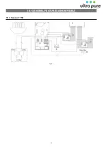
Страница 17: ...17 10 GENERAL FEATURES AND MODELS 10 4 Version 115V Fig 10 c...

Страница 18: ...ity at 20 C 0 50 S cm total hardness 0 25 mg l CaCO3 temporary hardness 0 15 mg l CaCO3 total quantity of dissolved solids cR depending on specific conductivity 1 dry residue at 180 C depending on spe...

Страница 19: ...Inactivity time for washing on next start R W 32 159 Parameter b3 Washing time fill drain R W 33 160 Parameter b4 Start delay time R W 34 161 Parameter b5 Operating hours for CL alarm R W 35 162 Param...

Страница 20: ...at 1 the humidifier excludes the external command signals external regulator or probes and uses the value of Integer 60 modbus 188 as like comand signal The humidity production can be managed in two...

Страница 21: ...of a signal Y from an external device The type of signal can be selected between the following standards 0 to 10 Vdc 2 to 10 Vdc 0 to 20 mA 4 to 20 mA Maximum humidifier production corresponding to th...

Страница 22: ...ituation is repeated alarm EP is activated which shuts down the unit If after a percentage of A8 set by parameter Ab default 70 the water is above the high level threshold atomised water production st...

Страница 23: ...llowing fields Percentage request sent to the Master Fig 3 Operating hour counter Fig 4 resettable pressing UP DOWN for 5 seconds see parameter d3 Unit alarms Fig 5 means no alarms are present resetta...

Страница 24: ...ctrical wiring from alarm relay output on the master to auxiliary input J17 on the slave and vice versa from alarm relay output on the slave to auxiliary input J17 on the master Main board Slave unit...

Страница 25: ...Main Board Connections MASTER UNIT Connections M 11 TX RX GND GND 1 RS485 Supervisore ON OFF 4 Main Board Connections SLAVE UNIT Connections 2 3 6 4 7 5 1 8 ON M9 M 11 M 11 M 11 6 6 6 TLan 2 Supervis...

Страница 26: ...Ultra Pure Systems 1855 E Southern Ave Mesa AZ 85204 800 729 5192 www ultrapureus com...

Отзывы: