


Since up to 64 brightness values can be entered in a gradient, 256 CVs are available for each bank. If a bank is selected for
programming via the CVs 31 and 32, the individual values are written to the CVs 257 - 512, with each course 64 CVs as
follows:
Bank 3 (CV31=8,CV32=3)
Bank 4 (CV31=8,CV32=4)
History 1: CVs 257 - 320
History 5: CVs 257 - 320
Course 2: CVs 321 - 384
History 6: CVs 321 - 384
Course 3: CVs 385 - 448
History 7: CVs 385 - 448
History 4: CVs 449 - 512
History 8: CVs 449 - 512
The gradients can be changed at any time, or replaced by your own gradients by changing the corresponding CVs in a value
range of 0 - 63.
The CVs 170 to 172 can be assigned to the outputs A0 to A2 one of these 8 PWM curves by entering the desired number 1 -
8 in the respective CV.
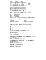
Each of the outputs light rear, A1 and A2 can be assigned one of 2 phase positions during playback. Thus, two outputs can be
generated, which flash in the changing clock. The required settings shall be entered in CV179:
Bit
Phase position of the outputs
CV179
Wert
0
A0h, phase 0°
0
A0h, phase 180°
1
1
A1, phase 0°
0
A1, phase position 180°
2
2
A2, phase 0°
0
A2, phase position 180°
4
Grade Crossing
If the bit7 (value 128) of the respective CV170 - 172 is set, the modulated effect is only activated if the CROSS output bit is set
via function mapping (see extended function mapping). If the CROSS output bit is not set, the output is constantly switched
on. If the CROSS output bit is switched off again via function mapping, the effect thus activated remains on until a hold time
programmed in CV180 has expired. This holding time results from the value of CV 180 multiplied by 100ms.
Servo control
The use of a servo on the decoder requires electronic expertise.
If a 1 is entered in CV166 and a function key number F0 - F28 is entered in CV167 (Servo1) and/or 168 (Servo2), a control
signal for a model user is output via the SUSI interface (Servo1 = Data, Servo2 = CLK, see graphic "Servo circuit for operating
a servo on SUSI or solder pads")
The servo positions and the rotation time can be set with the following CVs:
CV160 Servo 1 position 1 (function key off)
CV161 Servo 1 position 2 (function key on)
CV162 Servo 1 rotation time in 100ms steps
CV163 Servo 2 position 1 (function key off)
CV164 Servo 2 position 2 (function key on)
CV165 Servo 2 rotation time in 100ms steps
Advanced function mapping
The following settings of the decoder are only possible with the extended function mapping (CV 96 = 1).
The decoder supports advanced function mapping. In the extended function mapping, the simultaneous switching on or off of
several outputs, starting and braking delays, shunting, second dimming of the function outputs, SUSI as logic level output,
transfer of the function keys F22 to F28 to SUSI, as well as the setting of the CROSS-bit possible. These functions can be
switched on or off depending on linked conditions, such as function keys F0 to F44, direction of travel of the locomotive, as
well as loco stands or moves. These combinations are stored in two CV banks. In total, there are 7 available CV banks in the
decoder, each with 256 CVs. For this variety of combination possibilities, so many CVs are necessary that programming in the
conventional CV frame 1 to 1024 is no longer possible. Therefore, a special splitting into CV banks of 256 CVs (CV257 - 512)
is necessary.
Thus, the CVs 257 - 512 can be used multiple times. A similar procedure for handling CV banks already exists in our
IntelliSound modules. If you have already made settings there, you will certainly find your way around quickly.
Which of these CV banks should be programmed depends on the respective value of two "pointer CVs", the CVs 31 and 32.
The values of the "pointer CVs" do not change the meaning of the CVs 1 - 256 and are not relevant for driving operation.
Each CV bank of the extended function mapping consists of 16 lines with 16 entries. These 16 entries then form the
combination of switching condition and output. Since two CV banks are available for the extended function mapping, a total of
32 possible combinations for switching conditions and outputs can be realized.
TIP:
Before each programming process of the CVs 257 - 512, you should program the CVs 31 and 32 for the desired CV
bank. It is recommended to read these two "pointer CVs" before programming, so that wrong CV banks are not accidentally
programmed.
To facilitate programming, especially for extended function mapping, the programming software "Lok-Tool" can be used,
which is included with the digital programming and test station "DigiTest" from Uhlenbrock. This software is also available for
free download on our website www.uhlenbrock.de.
The CV programming of the extended function mapping in detail:
Pointer CVs:
CV31 = 8, CV32 = 0 for line 1 - 16 (Bank 1)
CV31 = 8, CV32 = 1 for lines 17 - 32 (Bank 2)
Each line consists of 16 entries (bytes) with the following meaning:
Entries (bytes) 1 - 6 specify the functions that must be
turned on
for the condition to be met.
Entries (bytes) 7 - 12 specify the functions that must be
turned off
for the condition to be met.
Entries (bytes) 13 - 16 specify
the outputs that
are turned on when the condition is met.
Each entry (byte) consists of a combination of 8 individual conditions (bits)
The bits 0 - 7 in the respective entries (bytes) for
the switching conditions On (bytes
1 - 6) and Off (
bytes 7
- 12) have the
following meaning:


