Uhlenbrock digital Intelli Drive 2 Скачать руководство пользователя страница 10

The output A0v

 should

 be switched off

 and

 the outputs

 A1 and

 A2 should

 be switched on. Furthermore,

 the 

second dimming for A2 (A2-P2) should

 be

 switched on

 and the CROSS

 bit

 should

 be

 set.


These outputs should only be activated if the loco moves backwards (

Drive.), the

 function key

 F14

 is switched on


and the

 function key F0 is switched off
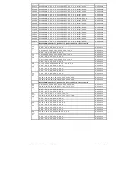
 

Bank 2, line 17

 -> CV31 = 8,

 CV32 = 1


Four CVs for output and three CVs for conditions to program


Lok fährt (

Fahr.

) -> CV-Nummer = 256 + (17 - 17) * 16 

+ 1 = 257 Lok fährt (

Fahr.

) -> Byte 1, Bit 6 = 1 -> CV 

257 = 64


F14 key

 on

 > CV number = 256 + (17 - 17) * 16 + 3 = 259 key


F14 on

 -> byte 3, bit 1 = 1 -> CV 259 = 2


Key

 F0 switched off

 + loco reverse (previous) switched off

 -

> CV number = 256 + (17 - 17) * 16 + 7 = 263


Key

 F0 switched off

 + loco reverse (previous) switched off

 -

> byte 7, bit 4 = 1 + bit 7 = 1-> CV 263 = 16 + 128 = 144


A0v

 should be switched off

 -

> CV number = 256 + (17 - 17) * 16 + 14 = 270


A0v

 should be switched off

 -

> byte 14, bit 0 = 0 -> CV 270 = 0


A1

 + A2

 switched on -

> CV number = 256 + (17 - 17) * 16 + 13 = 269


A1

 + A2

 switched on -

> byte 13, bit 0 = 1 + bit 1 = 1-> CV 269 = 1 + 2 = 3


A2-P2 switched on

 -> CV number = 256 + (17 - 17) * 16 + 15 = 271


A2-P2 switched on

 -> byte 15, bit 2 = 1 -> CV 271 = 4


CROSS

 bit

 set -

> CV number = 256 + (17 - 17) * 16 + 16 = 272


CROSS

-bit

 set -

> byte 16, bit 0 = 1 -> CV 272 = 1


To  facilitate  programming,  especially  for  extended  function  mapping,  the  programming  software  "Lok-Tool"  can  be 
used, which is included with the digital programming and test station "DigiTest" from Uhlenbrock. This software is also 
available for free download on our website www.uhlenbrock.de.


Second dimming of light and function outputs


The light and function outputs can be set to an alternative, ie second dimming (eg for a high beam). The settings of 
the  values  for  the  alternative  dimming  are  stored  in  the  CVs  150  (light),  151  (A1)  and  152  (A2).  In  the  extended 
function mapping (CV96 = 1), the alternative dimming of the CVs 150  - 152 is activated via  the  possible  conditions 
there (see "Extended function mapping).


Reset to factory setting (Reset)


To bring the decoder back to factory settings, two (CV8, CV59) can be used in the DCC programming, in the Moto-
rola programming a CV (CV59). In order to not rewrite all available areas, you can decide which areas should be 
brought into factory settings. The value 1-4 to be programmed sets the following CVs to factory settings:


1 = CV0 - 256, and CV257 - 512 (RailCom®

 Bank 7

)


CV31=0, CV32=255


2 = CV257 - 512


(RailCom Plus

®

 Banken 5 & 6)


CV31=1, CV32=0 and CV31=1, CV32=1


3 = CV257 - 512


(extended function mapping banks 1 & 2)


CV31=8, CV32=0 and CV31=8, CV32=1


4 = CV257 - 512


(PWM modulation function outputs banks 3 & 4)


CV31=8, CV32=3 and CV31=8, CV32=4


Содержание Intelli Drive 2

Страница 1: ...g track 8 Power consumption right red when the programming mode of the control panel is called up When reading or programming very small currents usually flow which do not damage the decoder in the ev...

Страница 2: ...de de_DE service download konformit tserkl rung index htm Our advantages for you If you have any questions we are here for you Internet FAQs can be found at www uhlenbrock de E Mail service uhlenbrock...

Страница 3: ...tion outputs A1 A2 in the user manual do not apply to the decoder 73115 with 6 pin NEM 651 interface Analog operation with DC voltage The locomotive decoder is suitable for analog operation with DC vo...

Страница 4: ...teps via CV 2 CV 5 and CV 6 0 Use characteristic curve from CV 67 94 16 5 Kurze Adresse CV 1 Register 1 0 Long address CV 17 and 18 32 Bit Konfiguration CV 50 Wert 0 Do not use Motorola 2nd address 0...

Страница 5: ...1st edition of this description remains valid If braking is initiated with a constant braking distance the decoder only responds to driving commands again when the locomotive has come to a standstill...

Страница 6: ...If such an output is switched on via a wireless button it is automatically switched off in the desired direction of travel CV113 2 A1 forward from CV113 4 A2 forward from CV113 8 A3 forward from CV113...

Страница 7: ...switch off automatically after an adjustable time without having to switch off the function key Furthermore the decoder can ensure that the coupling is only actuated for a short switch on moment with...

Страница 8: ...veral outputs starting and braking delays shunting second dimming of the function outputs SUSI as logic level output transfer of the function keys F22 to F28 to SUSI as well as the setting of the CROS...

Страница 9: ...la 256 line 1 16 bytes Formula 256 line 17 16 bytes The bit structure and the values to be programmed accordingly in the CVs are comparable to the configuration CVs of the decoder This means that ther...

Страница 10: ...CV 272 1 To facilitate programming especially for extended function mapping the programming software Lok Tool can be used which is included with the digital programming and test station DigiTest from...

Страница 11: ...From decoder software version 23 CV7 3rd edition 25 02 19...

Страница 12: ...ecoders Programming with a M rklin control unit eg 6021 With a M rklin control panel all CVs can be programmed but not read out The decoder can be put into programming mode in two ways a and b dependi...

Страница 13: ...255 255 Bit 0 0 DC analog operation direct current off 0 Bit 0 1 DC analog operation direct current on 1 Bit 2 0 Data format DCC from 0 Bit 2 1 Data format DCC a 4 Bit 3 0 Data format Motorola from 0...

Страница 14: ...ht A1 and A2 156Hz 0 Bit 3 1 Frequency light A1 and A2 24KHz 8 Bit 4 0 SUSI SUSI 0 Bit 4 1 SUSI A3 A4 output function mapping table 16 51 Decoder Konfiguration 2 Wert 0 135 3 131 Bit 0 0 Motor control...

Страница 15: ...value 200ms 16 240 131 Dynamic smoke generator control load threshold 0 255 5 132 Dynamic smoke generator control PWM normal operation 0 63 16 133 Dynamic smoke generator control PWM idle stand 0 63...

Страница 16: ...164 Servo control Servo 2 position 2 function key on 0 255 200...

Страница 17: ...es Switching on effect of light and function outputs A1 A2 0 7 0 bit 0 2 A0 to A2 Bit 0 effect off bit 1 effect on 189 Neon tubes turn on effect flash time value 5ms 0 255 20 190 Neon tubes turn on ef...

Страница 18: ...16 24 32 48 63 63 63 63 48 32 24 16 8 3 0 63 each until 0 0 0 0 0 0 0 0 0 0 0 0 0 0 0 0 0 63 each 320 3 8 16 24 32 48 63 63 63 63 48 32 24 16 8 3 0 63 each 0 0 0 0 0 0 0 0 0 0 0 0 0 0 0 0 0 63 each 3...

Отзывы: