


Firebox Polishers
Random flickering can be assigned to the outputs light, A1 and A2. This effect is used, for example, for the flickering of a
firebox.
CV181 = 1 -> flickering for light outputs, CV181 = 2 -> flickering for A1, CV181 = 4 -> flickering for A2.
A combination (sum of the individual values) is of course also possible here.
In the CV182 the settings for the flicker rhythm and for the brightness change are entered as follows:
Bits 0 - 3 change the flicker rhythm (value range 1 to 15).
Bits 4 - 6 change the brightness (value range 16, 32, 48, 64, 80, 96, 112).
With the value 128, the output is always bright, but can be combined with the value range 16 to 112.
Since only one value can be programmed in a CV, the flickering results from the sum of the individual values of the flicker
rhythm plus the sum of the individual values of the brightness (sum of bits 0 -3 plus sum of bits 4 - 6). The combination of all
bits leads to different, random flicker patterns. Here the rule is: "try".
Smoke generator control
At the outputs A1, A2 a smoke generator can be connected, which is controlled by the decoder load-dependent.
When stationary, the smoke output has the PWM according to CV133. If the locomotive starts, the output gets the
PWM=100%.
The engine can be stopped for 0-15 seconds (starting delay), so that the smoke generator heats up when stationary. At the
end of this time, the loco arrives, after which the output is controlled for another time (start-up time) with 100%. Then the
smoke output goes to the PWM in normal travel. In case of a load increase, the smoke output is controlled again with 100%
for the already defined start-up time. The necessary load increase (load threshold) can be set. For this purpose, the load
variable is used, which is also output for an IntelliSound module on the SUSI interface.
CV Meanings
The CV130 defines which of the two outputs A1, A2 is controlled with the smoke generator control and which time should apply to the
start-up delay. The value range 1-3 (1 = A1, 2 = A2, 3 = A1 & A2) defines the output and the value range 16 - 240 in steps of 16 the
starting delay, whereby a 16 step means one second starting delay. The sum of the individual values gives the value for the CV130.
Calculation: Start delay * 16 + output
The load threshold is entered in the CV131 in a value range from 0 to 127. The higher the value in 0.1s steps, the more the
output reacts to a load change.
The CV132 determines the PWM for the normal drive and the CV133 the PWM at the standstill.
Adjustable PWM - frequency of light and function outputs
The output voltage of a function output is pulse width modulated (PWM) with a predetermined frequency.
The function outputs of the decoder work in factory setting with a frequency of 156 Hz. This frequency can be increased to 24
kHz for all outputs A0 to A2. A typical application is the electrical coupling from ROCO. Only with the higher frequency do
these couplings no longer "flutter".
The frequency switching is adjustable in the CV50 in bit 3. Bit 3 = 0 -> 156Hz, Bit 3 = 1 -> 24KHz
Control of an electrical coupling
Electrical couplings consist of the finest copper wire windings. These usually react sensitively to permanent current flow, because they
become relatively hot. With appropriate settings, the decoder can ensure that the function outputs switch off automatically after an
adjustable time without having to switch off the function key. Furthermore, the decoder can ensure that the coupling is only actuated for a
short switch-on moment with an adjustable high PWM to safely lift the coupling. After this moment, less energy is required to keep the
clutch up. This, lower PWM, as well as the required holding time are also adjustable. If the used couplings do not disengage safely during
the first attempt, a number of coupling repetitions can also be set. When adjusting the clutch repetitions, "as many as necessary, as few
as possible" applies. So that a permanent repetition does not lead to the destruction of the coupling windings, an off time must be entered
in 0.1s steps, which the decoder always waits before performing another uncoupling process.
CV124 = Number of repetitions
CV125 = Switch-on time in 100ms steps with the PWM from CV117 (A1) or CV118 (A2)
CV126 = holding time in 100ms steps
CV127 = switch-off time in 100ms steps, (0=no clutch control)
CV128 = Hold PWM
CV129 = 2 -> Coupling for A1, CV129 = 4 -> Coupling for A2, CV129 = 6 -> Coupling for A1 & A2
Shunting ango, automatic uncoupling
A shunting line can only be activated if the electrical clutch control is activated via CV124-129. A shunting line is
triggered by one of the coupling outputs if the decoder level = 0: Function of a shunting line:
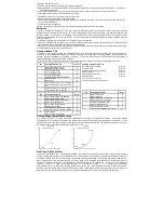
1. Locomotive moves with adjustable speed for an adjustable time (T1) against the current direction of travel (pressing)
2. Locomotive stops and changes direction
3. Uncoupling process and loco moves with the same speed step for an adjustable time T2 (back off)
4. Locomotive stops, now the locomotive has the original direction of travel again.
The CVs to be set are:
CV135 for the speed step of the shunting line (1-255). The value 0 specifies that no shunting ango takes place.
CV136 for the pressing time T1 in 100ms steps
CV137 for the rest time T2 in 100ms steps
Modulation of the PWM - output for the light and function outputs
The brightness of the outputs can be modulated by means of 64 different brightness values, which are periodically output as
PWM at the outputs. The period of playback is adjustable. It results from the value of CV178 multiplied by 64ms.
For the 8 PWM paths with up to 64 individual values, two banks (banks 3 & 4) á four PWM paths are available. In total, there
are 7 available CV banks in the decoder, each with 256 CVs. For this variety of combination possibilities, so many CVs are
necessary that programming in the conventional CV frame 1 to 1024 is no longer possible. Therefore, a special splitting into
CV banks of 256 CVs (CV257 - 512) is necessary.
Thus, the CVs 257 - 512 can be used multiple times. A similar procedure for handling CV banks already exists in our
IntelliSound modules. If you have already made settings there, you will certainly find your way around quickly.
Which of these CV banks should be programmed depends on the respective value of two "pointer CVs", the CVs 31 and 32.
The values of these two CVs point to the corresponding CV bank, here banks 3 and 4.The values of the "pointers
CVs do not change the meaning of CVs 1 - 256 and are not relevant for driving.
Setting of Bank 3 for programming the courses 1 to 4: CV31=8,CV32=3 Setting of Bank 4
for programming the courses 5 to 8: CV31=8,CV32=4 The following 8 PWM courses are
stored in the factory setting:
1 = Mars Light, 2 = Gyra Light, 3 = Oszi. Headlight, 4 = Stakato, 5 = Ditch Light, 6 = rotary Beacon, 7 = single Strobe, 8 =
double Strobe


