


EVK-IRIS-W10 - User guide
UBX-23007837 - R03
Setting up the evaluation board
Page 7 of 43
C1-Public
2
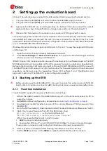
Setting up the evaluation board
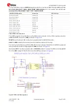
Connect the external power supply to the EVK as described in powering the board section.
•
The green status LED
(D10)
is lit when the internal EVK
3V3
supply is active.
•
The green status LED
(D19)
is lit when
3V3
supply to the MCU Link chip is active.
⚠
Approvals for IRIS-W1 are currently pending. For further information about the current
approval status, see the Qualifications and approvals section in the data sheet
⚠
Observe that this device is for evaluation only and is not FCC approved for resale.
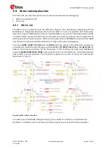
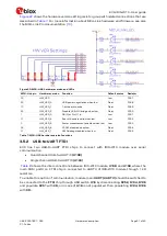
The operating system installs the correct COM port drivers automatically. The drivers need to
be installed only when you connect the unit to a new computer for the first time. For more
information about the COM ports and their configuration, see the FTDI FT231XQ-R Datasheet
Windows OS automatically assigns one COM port to the unit. To view the assigned COM ports
on Windows 10:
1.
Open the Control Panel and select Hardware and Sound.
2.
Click
Device Manager
in
Devices and Printers
. This opens the Device Manager window
where you can view the assigned COM ports.
IRIS-W10 open CPU module variants are used to develop custom software based on the NXP
MCUXpresso SDK, which provides all the APIs required for custom application development.
Before compiling custom software, you must configure the NXP MCUXpresso SDK for use with
the IRIS-W10 open CPU variant. For information about
f
or the working environment setup and
regulatory restrictions, see the respective “Open CPU software” and “Qualification and
approvals” sections of the IRIS-W10 system integration guide
2.1
Starting up the EVB
⚠
Before powering up the EVK-IRIS-W101, be sure to connect an antenna (or any 50
Ω RF
load) to the U.FL antenna connector (
J41
). Failing to do so can cause module malfunction.
2.1.1
Flash tool installation
To get the EVK ready with necessary flash tools and settings:
1.
Attach the USB-C cable to the USB3 MCU-Link port on the EVB and connect to PC to
power the module.
2.
Set
SW3
to default configuration, as described in
Automatic bootloader / strap-in
3.
Download and install the latest version of the J-Link software (V7.92g onwards) from
SEGGER
4.
Go to the NXP website
Download and install the latest MCU-Link software on the PC.
5.
Flash the J-Link software on the LPC chip (MCU-Link chip)
[
MCU-LINK_INSTALLER_WIN_3.1xx
] by running the script:
"
NXP\MCU-LINK_installer_3.1xx\scripts\program_JLINK.cmd
".
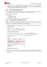
After the successful flashing of J-Link firmware:
LED1
turns red and blinks slowly.
Enumerated COM port "JLink CDC UART Port (COMxx)" is shown in Device Manager.
This process is necessary only during the initial setup of a newly acquired EVK.
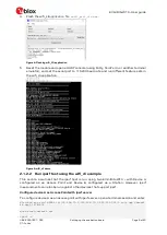
6.
Power cycle the module/EVK after flashing the software onto the LPC chip.
7.
Pull the
RFC2
pin to low on the
SW8
to enable the SWD interface of the module.


