EVK-IRIS-W10 - User guide
UBX-23007837 - R03
Hardware description
Page 13 of 43
C1-Public
3.1.1.2
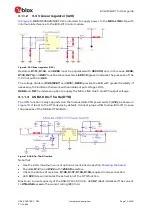
3.3 V Linear regulator (U20)
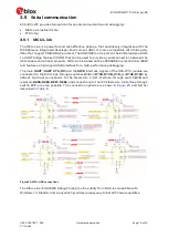
In
U20
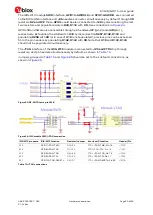
(NCP692MN33T2G is intended to supply power to the
MCU-LINK
chip with
minimum interference to the IRIS-W10 radio module.
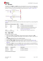
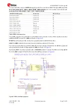
Figure 9: 3.3V linear regulator (U20)
Resistors
R151, R144
, and
R288
must be populated with
0603 0R,
and, in this case,
R208,
R145, R274,
and
R287
must be disconnected.
LED D19
(green) indicates the presence of the
3.3 V output from
U20.
The voltage dividers (
R145/R287
) and (
R151, R208
) provide the EVB with greater flexibility. If
necessary, the EVB can then work with variable output voltage LDOs.
R288
, and
R211
provide an option to supply the MCU-LINK chip from
U11
output voltage.
3.1.1.3
USB 2.0 On-The-Go (OTG)
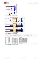
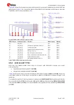
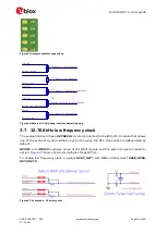
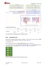
The OTG function is only supported on the module USB-OTG power switch (
U12),
as shown in
10. It is set to the OTG-device by default. Connect jumper
J14
to allow IRIS-W10 sense
the presence of the MUSB-OTG-VBUS.
Figure 10: USB On-The-GO switch
Note that:
•
Use the 2.4 A maximum current option as mentioned in section
•
Populate
R121
, and
R122
with
1206 0R
resistors.
•
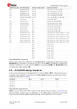
Check the status of resistors,
R106, R107, R108, R109,
required mode connection.
•
LED
D20
(Green) indicates the activation of the OTG function.
Maximum current capacity of the USB-OTG is 500 mA. LED
D2
(Red) indicates if the current
to
OTG-USB
exceeds the current rating (800 mA).


