EVK-JODY-W3 - User guide
UBX-20030840 - R02
Getting started
Page 9 of 29
3
Getting started
This chapter describes the basic settings and procedures necessary to get started with the JODY-
W3 EVK.
☞
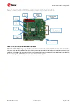
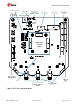
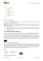
Figure 1 shows an overview of the EVK and its main connectors. For more detailed description
of the available connectors and configuration options, see section 4 .
Follow the procedure below to evaluate JODY-W3 series module using EVK-JODY-W3:
1.
Connect the internal or external antennas to the EVK:
o
EVK-JODY-W374 uses the two internal dual-band antennas by default for any Wi-Fi and
Bluetooth communication.
o
EVK-JODY-W377 uses one of the internal antennas by default for Bluetooth, and Wi-Fi is
configured to use SMA connectors.
o
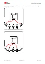
The two included external antennas connect to the selected SMA connectors, SMA1 and
SMA2, on the EVK-JODY-W377 board.
☞
For more information about the antenna configuration, see also section 4.10
2.
Set DIP switch SW503 to select the host interfaces for Wi-Fi and Bluetooth from the possible
combinations PCIE-UART, SDIO-UART or SDIO-SDIO, as described in section 4.9.
3.
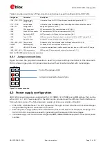
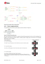
Configure the power supply source as described in section 4.3 and shown in Table 5. The most
common configuration uses the Wi-Fi host interface as the supply source, which can be either
PCIe or SDIO.
4.
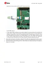
Connect the host interfaces to the host system. The EVK and supplied PCIe and SDIO adapters
use zero insertion force (ZIF) connectors and flat cables for connecting the adapters. To connect
the cable, gently flip up the small locking flap of the connector, align and insert the flat cable with
the blue marking pointing upwards, and then close the locking flap.
o
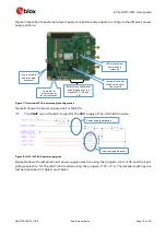
For PCIe connection, choose either the M.2 or the mini-PCIe adapter depending on the available
connector on the host platform. First, plug the adapter into the PCIe connector on the host
system and then connect it with the flat cable to the connector (J203) on the EVK, as shown
in Figure 2. The PCIe interface can be used for Wi-Fi communication with the JODY-W3 series

