EVK-JODY-W3 - User guide
UBX-20030840 - R02
Board description
Page 15 of 29
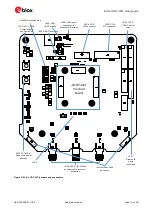
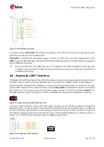
Figure 7 describes the external power supply connectors and jumpers to configure the different power
supply options.
Figure 7: Overview of EVK power supply configuration
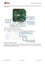
Figure 8 shows the power supply tree for the EVK.
☞
The
VBAT
rail on the EVK is used for the
3V3
supply of the JODY-W3 module.
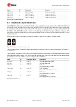
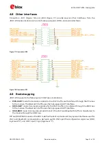
Figure 8: JODY-W3 EVK power supply tree
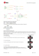
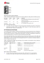
Figure 9 shows the external input power supply selection using the jumpers J104-J106 and the input
voltage selection for the JODY-W3 module using the jumpers J107-J110. The detailed settings are
further described in Table 5 and Table 7.
Jumpers for input
voltage muxing for
the module
Jumpers for
external power
supply selection
LEDs for external
power supply
selection
External connectors for
supplying each of the
signals 3V3, 1V8 and
VIO
Single external
power supply
connector
Power supply selection
Input voltage selection

