background image


C099-F9P - User guide 

UBX-18063024 - R12 

Using the C099-F9P


Page 15 of 40 

C1-Public  


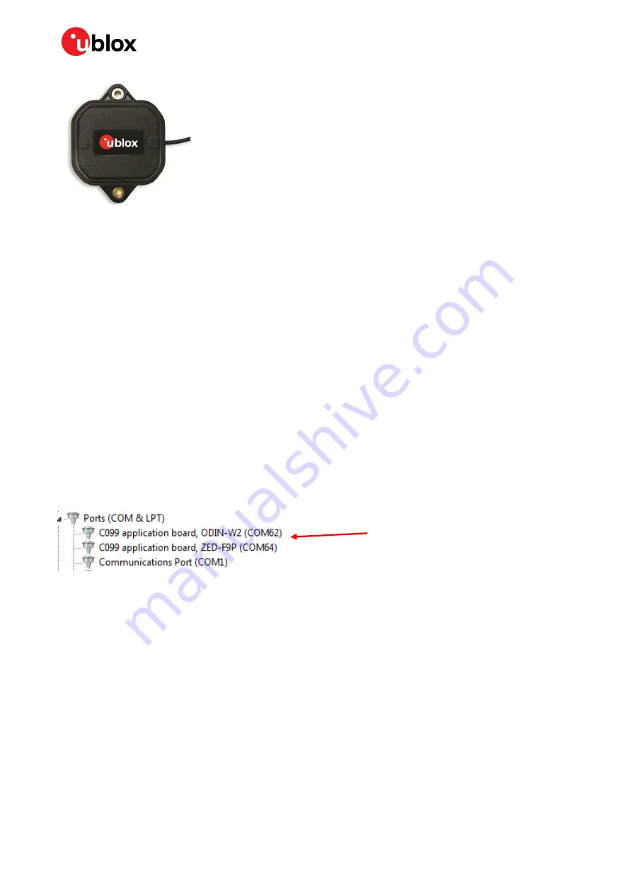
Figure 13: The supplied GNSS multi-band antenna 

4.3


User interfaces 

The C099-F9P has a number of fixed connection options besides the wireless modes. There is also an 
additional Arduino R3 / Uno interface for external host connection. 

The USB connector on the board provides connection via an on-board hub providing: 


An FTDI USB bridge to ZED-F9P UART1 and ODIN-W2 UART COM ports. 


Dedicated connection to the ZED-F9P USB port. 

4.3.1


FTDI USB bridge 

When the USB cable from the user’s PC is connected, a driver will load and set up two virtual serial 
ports, as shown below in Figure 14.  Additionally, a further serial VCP will be created to provide a direct 
connection with the ZED-F9P USB port. 


Ensure that the PC is connected to the internet to load the drivers from Windows Update. 

The first of these is connected to the ZED-F9P serial port and should be selected with u-center. The 
second serial device is for the ODIN-W2 module when using s-center. In Figure  14,  the  ODIN-W2 
connection is the first port (COM 62) and the ZED-F9P connection is the second port (COM 64). Port 
numbering can be different between individual PCs, but the same arrangement applies. 


Figure 14: Windows Device Manager COM port view 

In addition, a third VCP will be created corresponding to the ZED-F9P USB port. Windows 10 users will 
see a new VCP device in the Device Manager window when it loads a built-in driver. With older Windows 
installations, a driver will be loaded via Windows Update. In this case the device will be identified as a 
u-blox GNSS device in the Device Manager window. 

Open u-center (V18.12 or later), select the ZED-F9P serial port, and set the baud rate to 460800 to 
match the ZED-F9P default UART setting. Once connected, u-center shows typical received signal 
levels from multiple GNSS bands, see Figure 15 below. 

ZED-F9P and ODIN-W2 
COM ports installed 

Содержание C099-F9P-0-03

Страница 1: ...bed firmware User guide Abstract The C099 F9P board enables customers to evaluate RTK operation with the ZED F9P high precision GNSS receiver The board provides short range wireless connection via Blu...

Страница 2: ...ady u blox or third parties may hold intellectual property rights in the products names logos and designs included in this document Copying reproduction modification or disclosure to third parties of...

Страница 3: ...3 User interfaces 15 FTDI USB bridge 15 Command line interface of ODIN W2 16 4 4 Persistent ODIN W2 settings 17 Revert to factory default 17 5 Rover operation using NTRIP 18 5 1 PC hosting via u cent...

Страница 4: ...application firmware 29 u connectXpress software 29 8 Arduino header connections 31 Appendix 32 A Glossary 32 B C099 F9P antenna specification 32 B 1 Wi Fi Bluetooth antenna specification 32 C ODIN W...

Страница 5: ...via Wi Fi with ODIN W2 Mbed FW 4 Base and rover operation via Wi Fi with ODIN W2 Mbed FW This user guide is split into several useful sections including Section 2 C099 F9P quick start provides informa...

Страница 6: ...ulti band GNSS antenna and ground plane Wi Fi Bluetooth antenna USB interconnect cable Quick start guide USB to DC plug adapter cable Figure 1 C099 F9P board and antennas 1 2 Additional sources of inf...

Страница 7: ...the ZED F9P has obtained valid time information Figure 3 below shows a typical u center view with active satellite signal levels To operate the ZED F9P in RTK mode the GNSS antenna must be placed in...

Страница 8: ...18063024 R12 C099 F9P quick start Page 8 of 40 C1 Public Eventually the status will change to 3D DGNSS FIXED and the RTK LED will show a steady green light Figure 3 u center showing a view of the ZED...

Страница 9: ...SB a DC supply socket or by a Li Po lithium polymer battery The board has been designed using an Arduino form factor with the modules serial ports routed to the shield headers Note that a secondary US...

Страница 10: ...Figure 5 Main components and USB ports J9 J8 J3 J2 ZED F9P multi band GNSS RTK module ODIN W2 multi radio module USB ZED F9P USB and UART ODIN W2 UART ports GNSS antenna connector J2 J3 J8 J9 Arduino...

Страница 11: ...ages is being received and utilized but no RTK fixed mode has been achieved the yellow LED flashes When in RTK fixed mode the yellow LED is turned on The blue time pulse LED will flash at the default...

Страница 12: ...PP data packet transmission Blinking blue Failed SPP data packet transmission Blinking red Weak signal Bluetooth SPP connection failure Wi Fi access point and station AP and STA ready Yellow Ready to...

Страница 13: ...ditional USB power source Figure 9 Power connections Figure 10 Typical single cell 3 7 V Li Po battery with JST connector Follow all published safety advice for using bare cell Li Po batteries while c...

Страница 14: ...sabled In order to disable the ODIN W2 connect the safeboot jumper which forces the ODIN W2 into safeboot mode during the device start up See Figure 6 to locate the safeboot pins On average the ODIN W...

Страница 15: ...The first of these is connected to the ZED F9P serial port and should be selected with u center The second serial device is for the ODIN W2 module when using s center In Figure 14 the ODIN W2 connecti...

Страница 16: ...r guide 3 4 3 2 Command line interface of ODIN W2 The user controls the ODIN W2 through a command line interface CLI which supports Remote Procedure Call syntax as described below function_name run ar...

Страница 17: ...CLI but are not documented in this User guide 4 4 Persistent ODIN W2 settings By default the ODIN W2 starts in Bluetooth initiator role and the ODIN W2 UART1 is configured to use a 460800 baud rate H...

Страница 18: ...es in both UART and I2C interfaces in ZED F9P 5 1 PC hosting via u center The u center application includes an NTRIP client for PC hosting The u center User guide 3 provides help when setting NTRIP se...

Страница 19: ...google com store apps details id com lefebure ntripclient The application integrates an NTRIP client which forwards corrections received from a cellular or a wireless network to Bluetooth interface I...

Страница 20: ...T_C099 F9P_XYZW as shown in Figure 22 Figure 22 Windows 10 menu for adding a Bluetooth device 6 1 2 ODIN W2 as pairing initiator Once you have verified a working CLI connection use the following comma...

Страница 21: ...rver port incoming port at the host PC connect to the incoming COM port at u center prior to the CLI command on the C099 F9P bt_sppcli run MAC address After a successful connection the C099 F9P starts...

Страница 22: ...se and rover boards The on board ZED F9P and ODIN W2 are interconnected via I2C bus as in the Bluetooth operation Hence ensure that the desired ZED F9P messages are enabled for the I2C interface Base...

Страница 23: ...s link See section 6 3 1 3 Rover operation in Wi Fi STA mode for rover configurations 4 Apply ZED F9P base settings through u center by connecting to ZED F9P UART 1 port Any RTCM messages sent over th...

Страница 24: ...e current SSID by the following commands 1 Read the current SSID setting wifi_getssid run 2 Set and store a new SSID wifi_setssid run your_SSID Wi Fi connectivity between base and rover requires match...

Страница 25: ...eported by a CLI message from ODIN W2 UART1 interface and the LED indication yellow LED If the disconnection is not intended check the Wi Fi interface at the host PC Wi Fi channel congestion can be av...

Страница 26: ...able the configuration settings required for the C099 F9P The user has two possible serial communication channels to update ZED F9P UART1 and USB2 0 ports To update the ZED F9P connect to u center via...

Страница 27: ...down list This is shown in Figure 32 below Figure 31 Setting the required baud rate safeboot and training sequence options Then click the GO button at the bottom left corner of the window to begin the...

Страница 28: ...C099 F9P User guide UBX 18063024 R12 Firmware update Page 28 of 40 C1 Public Figure 33 Setting ZED F9P UART1 back to 460800 baud and saving it to flash memory...

Страница 29: ...users To ensure no settings persist over the firmware versions it is recommended to revert to factory default before uploading a new firmware Instructions can be found in section 4 4 1 Revert to facto...

Страница 30: ...S 0x8000000 COM port number After a succesful bootloader upload the actual u connectXpress software shall be uploaded while incrementing the memory index as shown below stm32flash exe b 115200 w ODIN...

Страница 31: ...specification The functions of each I O align as much as possible to the Arduino specified functions Check the pin functions and electrical compatibility before using with an Arduino R3 Uno see Figure...

Страница 32: ...nna Polarization Vertical Gain 3 dBi Impedance 50 Size 107 mm straight Type Monopole Connector Reverse polarity SMA plug inner thread and pin receptacle SMA plug inner thread and pin Comment To be mou...

Страница 33: ...uide UBX 18063024 R12 Appendix Page 33 of 40 D Mechanical board dimensions Figure 39 C099 F9P rev E dimensions E C099 F9P schematics The following pages show the complete schematic for the C099 F9P ev...

Страница 34: ...C099 F9P User guide UBX 18063024 R12 Appendix Page 34 of 40...

Страница 35: ...C099 F9P User guide UBX 18063024 R12 Appendix Page 35 of 40...

Страница 36: ...C099 F9P User guide UBX 18063024 R12 Appendix Page 36 of 40 RED...

Страница 37: ...C099 F9P User guide UBX 18063024 R12 Appendix Page 37 of 40...

Страница 38: ...C099 F9P User guide UBX 18063024 R12 Appendix Page 38 of 40...

Страница 39: ...ts R01 10 Jul 2018 ghun byou Initial release R02 19 Oct 2018 byou Updates for the C099 F9P rev B board revision R03 8 Nov 2018 olep Updates for Mbed3 FW in ODIN W2 R04 1 Feb 2019 olep Updates for Wi F...

Страница 40: ...ffice China Beijing Phone 86 10 68 133 545 E mail info_cn u blox com Support support_cn u blox com Regional Office China Chongqing Phone 86 23 6815 1588 E mail info_cn u blox com Support support_cn u...

Отзывы: