background image

56

Appendix B: Safety Notices

airFiber AF-24/AF-24HD User Guide

Ubiquiti Networks, Inc.

Содержание airFiber 24

Страница 1: ...24 GHz Point to Point Radio Models AF 24 AF 24HD ...

Страница 2: ......

Страница 3: ...uration 7 Hardware Installation 9 Connecting the GPS Antenna 11 Connecting Ethernet 12 Alignment 13 Chapter 3 Navigation 21 Accessing the airFiber Configuration Interface 21 Navigating the Interface 22 Notifications 23 Product Verification 23 Chapter 4 Dashboard 25 Link Status 25 Statistics 26 Device Status 27 Ethernet Connection Status 27 Chapter 5 Wireless Tab 29 Basic Wireless Settings 29 Wirel...

Страница 4: ...Device Maintenance 43 Chapter 9 Tools 45 Align Antenna 45 Discovery 46 Ping 46 Traceroute 46 airView 47 Log 49 Appendix A Specifications 51 Appendix B Safety Notices 55 Electrical Safety Information 55 Appendix C Warranty 57 Limited Warranty 57 Appendix D Compliance Information 59 Installer Compliance Responsibility 59 FCC 59 ISED Canada 59 RF Exposure Warning 59 CE Marking 59 RoHS WEEE Compliance...

Страница 5: ...operation within legal frequency channels output power and Dynamic Frequency Selection DFS requirements airFiber Configuration Interface System Requirements Microsoft Windows 7 Windows 8 Linux or Mac OS X Java Runtime Environment 1 6 or above Web Browser Mozilla Firefox Apple Safari Google Chrome Microsoft Edge or Microsoft Internet Explorer 11 Chapter 1 Overview Introduction Thank you for purchas...

Страница 6: ...Overview AF 24 Side 24 GHz Alignment Bracket Elevation Adjustment Azimuth Adjustment Ground Bonding Point Lock Bolts Lock Bolts Back Lock Bolts Lock Bolts Azimuth Adjustment 24 GHz Lock Bolts Lock Bolts Cover Lock Elevation Adjustment Port Cover Serrated Flange Nuts Serrated Flange Nuts ...

Страница 7: ...0 5 10 5 10 Alignment Bracket Elevation Adjustment Azimuth Adjustment Ground Bonding Point Lock Bolts Lock Bolts Back Lock Bolts Lock Bolts Lanyard Loop Lanyard Loop Azimuth Adjustment Cover Lock Port Cover Elevation Adjustment Serrated Flange Nuts Serrated Flange Nuts Lock Bolts Lock Bolts ...

Страница 8: ...Modulation Link Act Speed RX Power Master Slave RF Link Status LED State Status Data Speed Off 10 100 Mbps On 1000 Mbps Link Act Off No Ethernet Link On Ethernet Link Established Random Flashing Ethernet Activity AUX GPS Off No GPS Synchronization On Operational Strong Signal Normal Flash Operational Weak Signal Modulation Off x or 1x QPSK SISO Short Flash 2x QPSK MIMO Normal Flash 4x 16QAM MIMO L...

Страница 9: ... For more information about rain attenuation and rainfall zones here are a couple of resources The rain attenuation model described in ITU R Recommendation P 530 Propagation data and prediction methods required for the design of terrestrial line of sight systems which is available at www itu int rec R REC P 530 en The rainfall zones described in ITU R Recommendation P 837 Characteristics of precip...

Страница 10: ...ons with long cable runs up to 100 m We recommend that you protect your networks from harmful outdoor environments and destructive ESD events with industrial grade shielded Ethernet cable from Ubiquiti Networks For more details visit www ubnt com toughcable Installation Overview We recommend that you configure your paired airFiber radios before mounting Below is an overview of the installation wit...

Страница 11: ...quencies can be the same or different to suit local interference TX RX TX Slave Master Frequency A Frequency A RX Half Duplex Diagram Full Duplex The TX and RX Frequencies should be different TX RX TX RX Slave Master Frequency A Frequency B Full Duplex Diagram TX and RX Frequencies The TX Frequency on the Master must match the RX Frequency on the Slave and vice versa 1 Connect an Ethernet cable fr...

Страница 12: ...7 Configure the Wireless Security a Select the AES Key Type HEX or ASCII b For the Key field HEX Enter 16 bytes eight 16 bit HEX values 0 9 A F or a f You can omit zeroes and use colons similar to the IPv6 format Note The airFiber Configuration Interface supports IPv6 formats excluding dotted quad and double colon notation ASCII Enter a combination of alphanumeric characters 0 9 A Z or a z 8 Click...

Страница 13: ... mm 2 0 4 0 pole a Orient the Pole Mount Bracket around the pole so it is aimed in the direction of the other airFiber AF 24 b Insert the Carriage Bolts into the Pole Clamps c Secure the clamps with the Flat Washers Split Lock Washers and Hex Nuts Note orientation of slots Aim towards link 3 Loosen but do NOT remove the eight Lock Bolts located on the Alignment Bracket 4 Ensure that there is a 6 m...

Страница 14: ...all four screws are seated and fully tightened Grounding To attach a ground wire 1 Remove the nut from the Ground Bonding Point 2 Attach a ground wire min 8 AWG or 10 mm2 to the lug and replace the nut to secure the wire 3 Secure the other end of the ground wire to a grounded mast pole tower or grounding bar WARNING Failure to properly ground your airFiber units will void your warranty Note The gr...

Страница 15: ...ay as possible from the AF 24HD 1 Attach the GPS Antenna Mount to a pole using the included Metal Strap or attach it to a wall using the appropriate fasteners not included 2 Place the magnetic External GPS Antenna on the mount 3 Secure the cable of the External GPS Antenna to the mount with a Cable Tie 4 Turn the Cover Lock counterclockwise to the Unlocked icon Slide the Port Cover down to remove ...

Страница 16: ...port on the PoE Adapter 5 Connect the Power Cord to the PoE Adapter and then plug the Power Cord into a power outlet Note For added protection we recommend installing two GigE PoE surge protectors Install the first surge protector within one meter of the airFiber Data port and install the second surge protector at the ingress point of the location housing the wired network equipment Below is a dia...

Страница 17: ...r radios Determining the Received Signal Level There are three ways to determine the received signal level LED Display See the following section Using the LED Display airFiber Configuration Interface See Using the airFiber Configuration Interface on page 15 Audio tone Optional equipment required See Using the Audio Tone on page 18 Using the LED Display Establishing a Preliminary Link Adjust the po...

Страница 18: ...F Power dBm Note Values on the LED Display are displayed in negative dBm For example 61 represents a received signal level of 61 dBm which is stronger than 72 dBm 5 Master Adjust the azimuth and elevation of the Master until the strongest received signal level is displayed on the LED Display of the Master a Sweep the Azimuth AZ Adjustment Bolt of the Master through its adjustment range Master Azim...

Страница 19: ...he value remains constant while tightening the Lock Bolts If the LED value changes during the locking process loosen the Lock Bolts finalize the alignment of each airFiber AF 24 again and retighten the Lock Bolts 6 For each airFiber AF 24 attach the Port Cover and turn the Cover Lock to the Locked icon 24 GHz Using the airFiber Configuration Interface Before You Begin Access the airFiber Configura...

Страница 20: ...missions from the Master 1 For the Master and Slave ensure the eight Lock Bolts on the Alignment Bracket are sufficiently loose by spinning each washer by hand WARNING All Lock Bolts MUST be loose to avoid damage to the airFiber housing 2 For the Master and Slave ensure the Azimuth AZ and Elevation EL Adjustment Bolts are in the middle of their adjustment ranges Elevation EL Adjustment Bolt Azimut...

Страница 21: ...djustments on one end of the link using the Signal Strengths for the airFiber radio at the other end of the link Do NOT make simultaneous adjustments on the Master and Slave 1 Slave Adjust the azimuth and elevation of the Slave until the other installer sees the strongest Signal Strengths for the Master 2 Master Adjust the azimuth and elevation of the Master until the other installer sees the stro...

Страница 22: ... to 3 5 mm Stereo Phono Jack Note Wire colors may vary on RJ 12 cables 3 Attach the RJ 12 connector to the AUX port of the airFiber AF 24 4 Connect a pair of headphones or other listening device to the female audio jack Establishing a Preliminary Link Adjust the positions of the Master and the Slave to establish a preliminary link This requires the Master and Slave to be within a few degrees of th...

Страница 23: ... while the other installer listens to the audio tone at the other end of the link Do NOT make simultaneous adjustments on the Master and Slave 1 Slave Adjust the azimuth and elevation of the Slave until the other installer hears the highest pitch for the Master 2 Master Adjust the azimuth and elevation of the Master until the other installer hears the highest pitch for the Slave 3 Repeat steps 1 a...

Страница 24: ...20 Chapter 2 Installation airFiber AF 24 AF 24HD User Guide Ubiquiti Networks Inc ...

Страница 25: ...k Settings on page 33 for more details Accessing the airFiber Configuration Interface Connect to the airFiber Configuration Interface 1 Make sure that your host machine is connected to the LAN that is connected to the Config port on the airFiber AF 24 2 Configure the Ethernet adapter on your host system with a static IP address on the 192 168 1 x subnet for example 192 168 1 100 3 Launch your web ...

Страница 26: ...ge 37 System Controls system maintenance such as firmware updates device and date settings system account settings location settings device maintenance and configuration backup You can also change the language of the web management interface For details refer to System Tab on page 41 Displays the system log For details refer to Log on page 49 At the lower left and upper right of the window are ico...

Страница 27: ...n 180 seconds the countdown is displayed the device times out and resumes its earlier configuration Revert Changes Click Revert Changes to cancel all pending changes on all pages Save Changes Click Save Changes to immediately apply and save changes Product Verification The airFiber Configuration Interface will verify whether a product is genuine or counterfeit For a genuine airFiber AF 24 the airF...

Страница 28: ...24 airFiber AF 24 AF 24HD User Guide Ubiquiti Networks Inc ...

Страница 29: ...ays the distance between the local and remote radios The lock icon appears if the link is connected no icon is shown if there is no connection Local Device Device Name Displays the local device s customizable name or identifier The Device Name or host name is displayed in registration screens and discovery tools MAC Address Displays the local device s MAC address Receive Capacity Displays the loca...

Страница 30: ...th If the bar does not span the full width of the graph your link is not optimally aimed Below the signal strength graph the current modulation rate is displayed for the local or remote device 6x 64QAM MIMO 4x 16QAM MIMO 2x QPSK MIMO 1x QPSK SISO x QPSK SISO Above the graph the following are displayed Ideal Power Displays the expected receive power in dBm Chain Imbalance Displays the chain imbalan...

Страница 31: ... device s current altitude relative to sea level Synchronization airFiber uses GPS to synchronize the timing of its transmissions By default this option is Disabled Satellites Tracked Displays the number of satellites tracked by the GPS receiver GPS Signal Quality Displays Global Positioning System GPS signal quality as a percentage value on a scale of 0 100 Conducted TX Power Displays the conduct...

Страница 32: ...28 Chapter 4 Dashboard airFiber AF 24 AF 24HD User Guide Ubiquiti Networks Inc ...

Страница 33: ...y on the Master should be used as the RX Frequency on the Slave and vice versa For Half Duplex mode default the TX and RX Frequencies can be the same or different frequencies in response to local interference TX RX TX Slave Master Frequency A Frequency A RX Half Duplex Diagram For Full Duplex mode the TX and RX Frequencies should be different TX RX TX RX Slave Master Frequency A Frequency B Full D...

Страница 34: ...s allow greater throughput but generally require stronger RF signals and a higher Signal to Noise Ratio SNR By default Automatic Rate Adaptation is enabled and Maximum Modulation Rate is displayed This allows the airFiber AF 24 to automatically adjust the modulation rate to changing RF signal conditions Under certain conditions you may prefer to lock the Maximum Modulation Rate to a lower setting ...

Страница 35: ...haracters 0 9 A Z or a z Key Select the format of the MAC address HEX Enter 16 bytes eight 16 bit HEX values You can omit zeroes and use colons similar to the IPv6 format The default is 0000 0000 0000 0000 0000 0000 0000 0000 Note The airFiber Configuration Interface supports IPv6 formats excluding dotted quad and double colon notation ASCII Enter a combination of alphanumeric characters Using 128...

Страница 36: ...32 Chapter 5 Wireless Tab airFiber AF 24 AF 24HD User Guide Ubiquiti Networks Inc ...

Страница 37: ...use the same IP Address then you may lose access via the Data ports Management IP Address The AF 24 can use a static IP address or obtain an IP address from its DHCP server DHCP Keep the default DHCP to use DHCP reservation on your router to assign a unique IP Address The local DHCP server function of the router assigns a dynamic IP address gateway IP address and DNS address to the airFiber AF 24 ...

Страница 38: ... with its counterpart In this process the networked devices first share their capabilities and then choose the fastest transmission mode they both support To manually specify the maximum transmission link speed and duplex mode select one of the following options 100 Mbps Full 100 Mbps Half 10 Mbps Full or 10 Mbps Half If you are running extra long Ethernet cables a link speed of 10 Mbps could help...

Страница 39: ... capacity if the TX capacity goes below this threshold the Ethernet link will be dropped The default is 0 Mbps TX Capacity High Threshold This is the TX capacity required before a dropped link can be declared to be operational again The Ethernet link will remain down until the TX capacity reaches this threshold The default is 0 Mbps This setting should be greater than the TX Capacity Low Threshold...

Страница 40: ...36 airFiber AF 24 AF 24HD User Guide Ubiquiti Networks Inc ...

Страница 41: ...g Watchdog IP Address To Ping Specify the IP address of the target host to be monitored by Ping Watchdog Ping Interval Specify the time interval in seconds between the ICMP echo requests that are sent by Ping Watchdog The default value is 300 seconds Startup Delay Specify the initial time delay in seconds until the first ICMP echo requests are sent by Ping Watchdog The default value is 300 seconds...

Страница 42: ...and password SSH Server The following SSH Server parameters can be set SSH Server Enables SSH access to the airFiber AF 24 Server Port Specify the TCP IP port of the SSH Server Password Authentication If enabled you must authenticate using administrator credentials to grant SSH access to the airFiber AF 24 otherwise an authorized key is required Authorized Keys Click Edit to import a public key fi...

Страница 43: ...em log messages are sent to a remote server which is specified in the Remote Log IP Address and Remote Log Port fields Remote Log IP Address The host IP address that receives syslog messages Properly configure the remote host to receive syslog protocol messages Remote Log Port The TCP IP port that receives syslog messages 514 is the default port for the commonly used system message logging utiliti...

Страница 44: ...40 Chapter 7 Services Tab airFiber AF 24 AF 24HD User Guide Ubiquiti Networks Inc ...

Страница 45: ...Displays the build number of the firmware version Check for Updates By default the firmware automatically checks for updates To manually check for an update click Check Now Upload Firmware Click this button to update the airFiber AF 24 with new firmware The airFiber AF 24 firmware update is compatible with all configuration settings The system configuration is preserved while the AF 24 is updated ...

Страница 46: ...2 enter 04 05 2012 in the field System Accounts You can change the administrator password to protect your device from unauthorized changes We recommend that you change the default administrator password when initially configuring the device Administrator Username Specifies the name of the administrator The maximum length is 31 characters Change Password Click Change to change the administrator pas...

Страница 47: ...onfiguration are displayed in the Wireless Network Advanced Services and System tabs of the airFiber Configuration Interface Reset to Factory Defaults Click this option to reset the airFiber AF 24 to the factory default settings This option will reboot the airFiber AF 24 and all factory default settings will be restored We recommend that you back up your current system configuration before resetti...

Страница 48: ...44 Chapter 8 System Tab airFiber AF 24 AF 24HD User Guide Ubiquiti Networks Inc ...

Страница 49: ...al Displays the actual power level bar graph and first number and ideal power level second number in dBm of the received signal for chain 0 and chain 1 Changing the RX Gain on the Wireless tab does not affect the Signal Strength values displayed on the Antenna Alignment window However if Overload is displayed to indicate overload condition decrease the RX Gain Refer to RX Gain on page 30 for more ...

Страница 50: ...twork devices Network Ping Select Destination IP You have two options Select a remote system IP from the drop down list which is generated automatically Select specify manually and enter the IP address in the field displayed below Packet Count Enter the number of packets to send for the ping test Packet Size Specify the size of the packet Start Click this button to start the test Packet loss stati...

Страница 51: ...umber of frames per second FPS gathered since the start of the airView session or since the Reset All Data button was last clicked The wider the interval amplitude the fewer the FPS will be gathered Reset All Data Click to reset all gathered data Use this option to analyze the spectrum for another location or address File Menu Click Exit to end the airView session View Menu Enable Chart Panel 1 to...

Страница 52: ...e Waterfall View s legend top right corner provides a numerical guide associating the various colors to power levels in dBm The low end of that legend left is always adjusted to the calculated noise floor and the high end right is set to the highest detected power level since the start of the airView session Channel Usage Displays each Wi Fi channel s relative crowdedness as a percentage The airVi...

Страница 53: ... Enable box to enable the maximum power trace When enabled the maximum power trace is represented by the blue area on the Real time chart which displays the maximum received power level data since the start of the airView session To enable a shaded blue area check the Shaded Area box To display only a blue outline without the shaded area uncheck the Shaded Area box Frequency Range Select the ampli...

Страница 54: ...50 Chapter 9 Tools airFiber AF 24 AF 24HD User Guide Ubiquiti Networks Inc ...

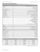
Страница 55: ...nk Activity Configuration Port Speed Configuration Port Link Activity GPS Synchronization Modulation Mode Master Slave RF Status 1 Two Digit LED Display Calibrated in dBm Button Reset Interface Data Port 1 10 100 1000 Ethernet Port Configuration Port 1 10 100 Ethernet Port Auxiliary Port 1 RJ 12 Alignment Tone Port System Maximum Throughput 1 4 Gbps Maximum Range 13 km 8 mi Packets per Second 1 Mi...

Страница 56: ...ion Channel Bandwidth 100 MHz Operating Channels 24 1 GHz 24 2 GHz Modulation 64QAM MIMO 16QAM MIMO QPSK MIMO QPSK SISO x QPSK SISO Integrated Split Antenna TX Gain 33 dBi RX Gain 38 dBi Beamwidth 3 5 Front to Back Ratio 70 dB Polarity Dual Slant Polarization Cross Polarity Isolation 28 dB AF 24 Capacity Mbps Rate Modulation 100 MHz Channel Width 6x 64QAM MIMO 1500 0 4x 16QAM MIMO 1000 0 2x QPSK M...

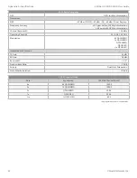
Страница 57: ...k Activity Configuration Port Speed Configuration Port Link Activity GPS Synchronization Modulation Mode Master Slave RF Status 1 Two Digit LED Display Calibrated in dBm Button Reset Interface Data Port 1 10 100 1000 Ethernet Port Configuration Port 1 10 100 Ethernet Port Auxiliary Port 1 RJ 12 Alignment Tone Port System Maximum Throughput 1 4 Gbps Maximum Range 13 km 8 mi Packets per Second 1 Mil...

Страница 58: ...idth 100 MHz Operating Channels 24 1 GHz 24 2 GHz Modulation 256QAM MIMO 64QAM MIMO 16QAM MIMO QPSK MIMO QPSK SISO x QPSK SISO Integrated Split Antenna TX Gain 33 dBi RX Gain 40 dBi Beamwidth 3 5 Front to Back Ratio 70 dB Polarity Dual Slant Polarization Cross Polarity Isolation 28 dB AF 24HD Capacity Mbps Rate Modulation 100 MHz Channel Width 8x 256QAM MIMO 2000 0 6x 64QAM MIMO 1500 0 4x 16QAM MI...

Страница 59: ...e parts inside this equipment Service should be provided only by a qualified service technician 3 This equipment is provided with a detachable power cord which has an integral safety ground wire intended for connection to a grounded safety outlet a Do not substitute the power cord with one that is not the provided approved type Never use an adapter plug to connect to a 2 wire outlet as this will d...

Страница 60: ...56 Appendix B Safety Notices airFiber AF 24 AF 24HD User Guide Ubiquiti Networks Inc ...

Страница 61: ...processed and will be returned freight collect or subject to disposal Information on the RMA process and obtaining an RMA number can be found at www ubnt com support warranty Disclaimer EXCEPT FOR ANY EXPRESS WARRANTIES PROVIDED HEREIN UBIQUITI NETWORKS ITS AFFILIATES AND ITS AND THEIR THIRD PARTY DATA SERVICE SOFTWARE AND HARDWARE PROVIDERS HEREBY DISCLAIM AND MAKE NO OTHER REPRESENTATION OR WARR...

Страница 62: ...es states and provinces do not allow the exclusion or limitation of liability for incidental or consequential damages so the above limitation may not apply to you EXCEPT TO THE EXTENT ALLOWED BY LOCAL LAW THESE WARRANTY TERMS DO NOT EXCLUDE RESTRICT OR MODIFY AND ARE IN ADDITION TO THE MANDATORY STATUTORY RIGHTS APPLICABLE TO THE LICENSE OF ANY SOFTWARE EMBEDDED IN THE PRODUCT TO YOU The United Na...

Страница 63: ... cause harmful interference in which case the user will be required to correct the interference at his own expense ISED Canada CAN ICES 3 A NMB 3 A This device complies with ISED Canada licence exempt RSS standard s Operation is subject to the following two conditions 1 This device may not cause interference and 2 This device must accept any interference including interference that may cause undes...

Страница 64: ... eléctricos y electrónicos a través de los puntos de recogida que ponen a su disposición el gobierno y las autoridades locales Al desechar y reciclar correctamente estos aparatos estará contribuyendo a evitar posibles consecuencias negativas para el medio ambiente y la salud de las personas Si desea obtener información más detallada sobre la eliminación segura de su aparato usado consulte a las au...

Страница 65: ...www ubnt com compliance Íslenska Icelandic Hér með lýsir UBIQUITI NETWORKS yfir því að AF 24 AF 24HD er í samræmi við grunnkröfur og aðrar kröfur sem gerðar eru í tilskipun 2014 53 EU Fullur texti ESB samræmisyfirlýsing er að finna á eftirfarandi netfangi www ubnt com compliance Italiano Italian Il fabbricante UBIQUITI NETWORKS dichiara che il tipo di apparecchiatura radio AF 24 AF 24HD è conforme...

Страница 66: ...62 Appendix E Declaration of Conformity airFiber AF 24 AF 24HD User Guide Ubiquiti Networks Inc ...

Страница 67: ...rks Inc 685 Third Avenue 27th Floor New York NY 10017 USA www ubnt com Online Resources Support ubnt link airFiber Support Community community ubnt com airfiber Downloads www ubnt com download airfiber 2012 2018 Ubiquiti Networks Inc All rights reserved Ubiquiti Ubiquiti Networks the Ubiquiti U logo the Ubiquiti beam logo airFiber airOS airView EdgeRouter TOUGHCable and UNMS are trademarks or regi...

Страница 68: ...w w w u b n t c o m ...

Отзывы: