15
Chapter 2: Installation
airFiber AF-24/AF-24HD User Guide
Ubiquiti Networks, Inc.
Fine-Tuning the Link
The
Azimuth (AZ)
and
Elevation (EL) Adjustment Bolts
of
the
Alignment Bracket
adjust the azimuth and elevation
within a range of ±10°. For accurate alignment, make
adjustments on one end of the link while the other
installer reports the received signal level at the other end
of the link. Do NOT make simultaneous adjustments on
the
Master
and
Slave
.
1.
Slave
Adjust the azimuth and elevation of the
Slave
until the other installer sees the strongest received
signal level displayed on the LED Display of the
Master
.
2.
Master
Adjust the azimuth and elevation of the
Master
until the other installer sees the strongest received
signal level displayed on the LED Display of the
Slave
.
3. Repeat steps 1 and 2 until you achieve a symmetric
link, with the received signal levels within 1 dB of each
other. This ensures the best possible data rate between
the airFiber radios.
4. Lock the alignment on both airFiber radios by
tightening all eight
Lock Bolts
on the
Alignment Bracket.
5. Observe the LED Display on each airFiber AF-24
to ensure that the value remains constant while
tightening the
Lock Bolts
. If the LED value changes
during the locking process, loosen the
Lock Bolts
,
finalize the alignment of each airFiber AF-24 again, and
retighten the
Lock Bolts
.
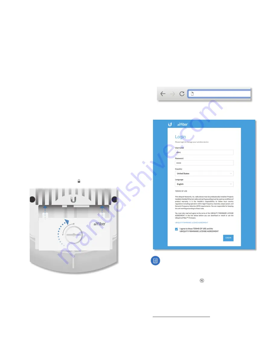
6. For each airFiber AF-24, attach the
Port Cover
and turn
the
Cover Lock
to the
Locked
icon.
24 GHz
Using the airFiber Configuration Interface
Before You Begin
Access the airFiber Configuration Interface:
1. Make sure that your computer that is connected to the
Config
port on the airFiber AF-24.
2. Configure the Ethernet adapter on your computer
with a static IP address on the 192.168.1.x subnet (for
example, 192.168.1.100).
3. Launch your web browser. Type
http://192.168.1.20
in
the address field and press
enter
(PC) or
return
(Mac).
https://192.168.1.20
4. The login screen will appear. Enter
ubnt
in the
Username
and
Password
fields, and click
Login
.
Note:
U.S. product versions are locked to the U.S.
Country Code to ensure compliance with FCC
regulations.
5. The
Dashboard
of the airFiber Configuration Interface
appears. Click the
Tools
drop-down list at the top
right corner of the page.
6. Click
Alignment
. You will use the
Align Antenna
tool
to point and optimize the antenna in the direction of
maximum link signal. (The
Antenna Alignment
window
is designed to refresh every 250 milliseconds. See
“Align Antenna” on page 45
for more details.)
Содержание airFiber 24
Страница 1: ...24 GHz Point to Point Radio Models AF 24 AF 24HD ...
Страница 2: ......
Страница 24: ...20 Chapter 2 Installation airFiber AF 24 AF 24HD User Guide Ubiquiti Networks Inc ...
Страница 28: ...24 airFiber AF 24 AF 24HD User Guide Ubiquiti Networks Inc ...
Страница 32: ...28 Chapter 4 Dashboard airFiber AF 24 AF 24HD User Guide Ubiquiti Networks Inc ...
Страница 36: ...32 Chapter 5 Wireless Tab airFiber AF 24 AF 24HD User Guide Ubiquiti Networks Inc ...
Страница 40: ...36 airFiber AF 24 AF 24HD User Guide Ubiquiti Networks Inc ...
Страница 44: ...40 Chapter 7 Services Tab airFiber AF 24 AF 24HD User Guide Ubiquiti Networks Inc ...
Страница 48: ...44 Chapter 8 System Tab airFiber AF 24 AF 24HD User Guide Ubiquiti Networks Inc ...
Страница 54: ...50 Chapter 9 Tools airFiber AF 24 AF 24HD User Guide Ubiquiti Networks Inc ...
Страница 60: ...56 Appendix B Safety Notices airFiber AF 24 AF 24HD User Guide Ubiquiti Networks Inc ...
Страница 66: ...62 Appendix E Declaration of Conformity airFiber AF 24 AF 24HD User Guide Ubiquiti Networks Inc ...
Страница 68: ...w w w u b n t c o m ...


