background image

PAGE 4 OF 15 

1220 IH-8928

NOTE: The end user is responsible for ensuring that 
all employees involved in the operation of this 
hopper understand and follow these instructions.

Suitable for use indoors and outdoors in most common 

industrial and commercial locations. Unit is intended 

for use in conjunction with a rider fork truck to dump 

non-hazardous refuse into typical refuse containers.
Hopper is self-dumping and has a 70° dump angle. It 

is operated by a release cable held by the fork truck 

driver.

NOTE: OSHA 29CFR, Chapter XVII, Part 1910.178 
(a)(4) states, 

"

Modifications and additions 

which affect capacity and safe operation (of 
a fork truck) shall not be performed by the 
customer or user without manufacturer's prior 
written approval. Capacity, operation and 
maintenance instruction plates, tags or decals 
shall be changed accordingly.

"

 And, 1910.178 

(a)(5) states that 

"

If (a fork) truck is equipped 

with front-end attachments other than factory 
installed attachments, the user shall request that 
the truck be marked to identify the attachments 
and show the approximate weight of the truck 
and attachment combination at maximum 
elevation with load laterally centered.

"

LOADING

Load rating, in pounds, is shown on the capacity label 

located on the rear (fork truck side) of the hopper.

WARNING! To avoid the risk of sustaining  
serious personal injuries:

•  Verify that the dumper is locked in the fully 

upright position before loading the hopper.   

•  Do not exceed the dumper's (and if portable, 

its casters') load ratings or fill the hopper 
above the top of the hopper's sides. Injury 
to personnel or permanent damage to the 

equipment could result from overloading.

DUMPING

WARNING! To minimize the risk to yourself and 
others, always carefully watch the hopper and 
its load when transporting or emptying it.

1.  From the rear of the dumper, insert the fork truck's 

forks into the dumper's fork pockets. The fork truck's 

forks are to be inserted completely.

2.  Secure the dumper to the fork truck's fork carriage 

with the attached safety restraint. Wrap the restraint 

chain around a part of the fork carriage and attach 

the chain's snap hook to the chain (through one of 

the chain links) with as little slack as possible.

3.  Place the release cable within reach of the fork 

truck driver in preparation for dumping.

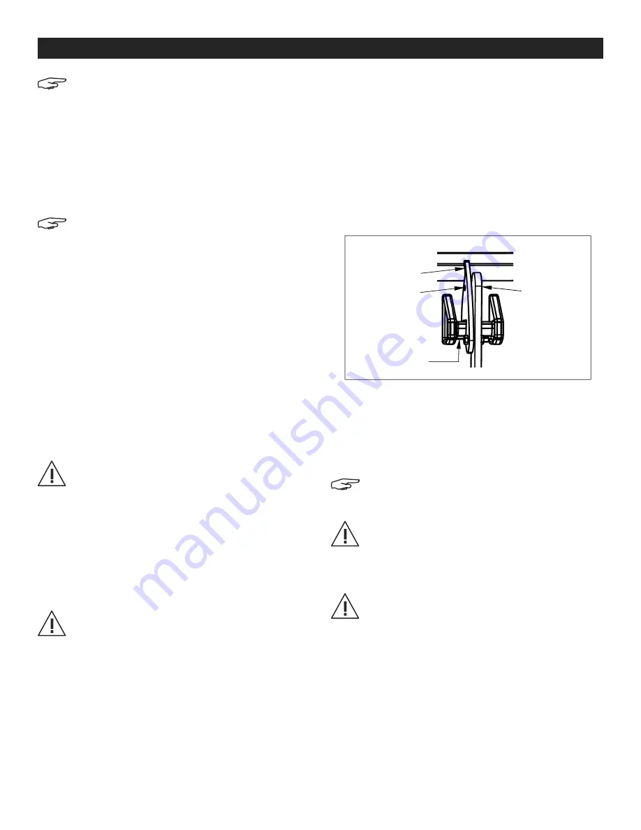
4.  The dumper chute cannot dump unless the latch 

is unlocked. To unlock the latch, pull the finger tab 

at the top end of the latch lock bracket until the 

bracket disengages the latch bar. (See Figure 7)

5.  Move the front of the dumper into position at the 

side of the dumpster or refuse container.

6.  Lift and tilt the fork truck mast forward until the 

dumper is at the appropriate height to allow the 

front of its frame to make contact with the top of the 

container's side.

NOTE: Allow clearance for the hopper to 

completely rotate forward without contacting 
any obstructions.
WARNING! Keep all personnel clear of the 
dumper and the dumping area before 

releasing the hopper.

7.  The release cable can be pulled from the fork truck 

operator's position.

WARNING! Never wrap the dumper's release 
cable around any body part.

8.  Tilt the fork truck mast back, then back away from 

the refuse container and slowly lower the dumper. 

Dumper will automatically rotate backward and 

lock in the upright position.

OPERATION

Figure 7

Finger Tab

Latch Lock  

Bracket

Latch Lever

Latch Bar

Содержание H-8928

Страница 1: ...t the dumper is locked in place and secured to the fork truck s fork mast before transporting it or raising it off the ground 7 Maintenance and repairs are to be done only by personnel qualified to perform the required work 8 Use only factory approved replacement parts 9 Assembly must be performed by suitably trained personnel with access to the appropriate equipment and tools 10 Adding casters wi...

Страница 2: ...re 2 NOTE Install release lever rod from back of hopper forklift side into front dumping side 4 Slide rod into guide ring far enough to ensure it clears the lock release lever NOTE The release lever rod should be placed over frame cross brace but underneath main connecting pin See Figure 3 Hopper x 1 Release Lever Rod x 1 Bumper Plate x 1 Clevis Pin Small x 1 Clevis Pin Large x 1 Cotter Pin Small ...

Страница 3: ...See Figure 5 7 Slide large clevis pin through bumper plate and fork pocket base Attach large cotter pin 8 Rotate dumping hopper back to the upright position See Figure 6 NOTE Ensure lock release lever engages and chute latches properly QUICK RELEASE ASSEMBLY CONTINUED Figure 4 Figure 5 Figure 6 Bumper Plate Large Clevis Pin Small Clevis Pin Large Cotter Pin Small Cotter Pin View From Forklift Side...

Страница 4: ...nnel or permanent damage to the equipment could result from overloading DUMPING WARNING To minimize the risk to yourself and others always carefully watch the hopper and its load when transporting or emptying it 1 From the rear of the dumper insert the fork truck s forks into the dumper s fork pockets The fork truck s forks are to be inserted completely 2 Secure the dumper to the fork truck s fork...

Страница 5: ...formed by suitably trained personnel with access to the appropriate equipment and tools BEFORE EACH USE Inspect for the following 1 Frayed or damaged pull cable 2 Damage or structural deformation to the hopper or the dumper s frame 3 Proper locking of the latch lock bracket 4 Unusual noise or binding while dumping or evidence thereof 5 Evidence of fatigue or damage to the securing chain its attach...

Страница 6: ...reparaciones se deben realizar solo por personal calificado para el trabajo requerido 8 Use solo partes de repuesto aprobadas de fábrica 9 El ensamble se debe llevar a cabo por personal debidamente capacitado que tenga acceso al equipo y las herramientas adecuadas 10 Agregar ruedas reducirá la capacidad de carga rodante Las capacidades son Ruedas de acero 544 kg 1 200 lbs rueda Ruedas de caucho mo...

Страница 7: ...ración de la parte posterior de la tolva lado del montacargas en el lado frontal de descarga 4 Deslice la varilla en el anillo guía lo suficiente hasta despejar el seguro de la palanca NOTA La varilla de la palanca de liberación se debe colocar sobre el soporte transversal del armazón pero debajo del pasador de conexión principal Vea Diagrama 3 1 Tolva 1 Varilla de la Palanca de Liberación 1 Placa...

Страница 8: ...e instale el perno de leva chico y el pasador de chaveta chico Vea Diagrama 4 6 Instale la placa parachoque en la base del hueco para horquillas usando el perno de leva y pasador de chaveta largos Vea Diagrama 5 7 Deslice el pasador de chaveta grande a través de la placa parachoque y la base del hueco para horquillas Fije el pasador de chaveta grande 8 Gire la tolva autovaciable de nuevo a la posi...

Страница 9: ...CIA Para minimizar el riesgo a usted o a otros siempre observe la tolva y su carga con cuidado al transportarla o vaciarla 1 Desde la parte posterior de la caja de volteo inserte las horquillas del montacargas en los huecos para horquillas de la caja de volteo Las horquillas del montacargas se deben insertar completamente 2 Asegure el volquete al portahorquillas del montacargas con el sistema de r...

Страница 10: ...nes se deben llevar a cabo por personal debidamente capacitado que tenga acceso al equipo y las herramientas adecuadas ANTES DE CADA USO Inspeccione lo siguiente 1 Cable de tracción deshilachado o dañado 2 Daños o deformación estructural a la tolva o al armazón de la caja de volteo 3 Aseguramiento adecuado del soporte de bloqueo de pestillo 4 Ruido inusual o atascamiento al vaciar o evidencia de e...

Страница 11: ...d entretien et de réparation doit être effectuée uniquement par un personnel qualifié pour réaliser les travaux demandés 8 Utilisez uniquement des pièces de remplacement approuvées par le fabricant 9 Le montage doit être exécuté par du personnel dûment qualifié ayant accès à l équipement et aux outils appropriés 10 L ajout de roulettes réduira la capacité de charge de roulement Les capacités sont ...

Страница 12: ...asser la tige du levier de dégagement de l arrière de la benne côté chariot élévateur sur le côté avant de déchargement 4 Faites glisser la tige dans l anneau de guidage suffisamment loin pour libérer le levier de dégagement du verrou REMARQUE La tige du levier de dégagement doit être placée par dessus la traverse du châssis mais en dessous de la goupille principale de raccordement Voir Figure 3 B...

Страница 13: ...lez la petite goupille de chape et la petite goupille fendue Voir Figure 4 6 Installez la plaque de butée sur la base du passage de la fourche en utilisant la grande goupille de chape et la grande goupille fendue Voir Figure 5 7 Faites glisser la grande goupille de chape à travers la plaque de butée et la base du passage de la fourche Fixez la grande goupille fendue 8 Remettez la benne en position...

Страница 14: ... benne au delà de ses rebords Une surcharge peut blesser le personnel ou endommager l équipement de façon permanente DÉCHARGEMENT AVERTISSEMENT Pour votre sécurité et celle d autrui ainsi que pour minimiser les risques surveillez toujours attentivement la benne et sa charge pendant le transport et au moment de la vider 1 De l arrière de la benne insérez les fourches du chariot élévateur dans les p...

Страница 15: ...ers potentiels doivent effectuer le dépannage et les réparations de cet équipement Les réparations doivent être effectuées par du personnel dûment formé ayant accès à l équipement et aux outils appropriés AVANT CHAQUE UTILISATION Inspectez les éléments suivants 1 Câble de traction effiloché ou endommagé 2 Dommage ou déformation de la structure de la benne ou de son châssis 3 Verrouillage approprié...

Отзывы: