XPLR-HPG-1 - User guide
UBX-23000692 - R01
Hardware description
Page 27 of 37
C1-Public
Wheel tick (WT) and direction (DIR) data is communicated from a vehicle sensor to the C213
baseboard through the J2 (JST 1mm pitch 3-pin) connector. The
WT_IN
and
DIR_IN
input signals can
be monitored on test points TP34 and TP37 and are regulated using two Zener diodes, D6A and D7A.
The optocoupler U5 provides the electrical isolation and switching step-down between the external
(3.3 V
–
24 V) input signals and standard 3.3 V logic output voltage levels,
WT_OUT
and
DIR_OUT
.
The conditioning circuit opto-isolates, filters, and then references the signals to 3.3
V using a dual
buffer (SN74LVC2G07) in combination with the pull-up resistors, R60 and R61. The circuit prepares
the signals for input to the NORA-W106 multiradio module and the GNSS RTK 2 (ZED-F9R) Click
board though the J5 header and two wires.
The signal conditioning circuit can also be used with quadrature encoder signals that are input to
NORA-W106. The speed/position values can be forwarded to ZED-F9R through the J5 header or can
be communicated to it through NORA-W106 over a serial interface (I2C or UART).
The pin connections for the wheel tick and direction signals are shown in
NORA-W106 pin
ESP32-S3 GPIO
Function
B6
XTAL_32K_N / GPIO16 (A)
WT/DIR-DIR
C6
XTAL_32K_P / GPIO15 (A)
WT/DIR-WT
Table 9: Wheel tick / direction NORA-W106 signals
2.2
Click boards
XPLR-HPG-1 comes with three Click boards:
•
featuring the ZED-F9R multi-band GNSS module for high-precision GNSS
•
featuring the NEO-D9S satellite receiver for L-band correction
•
featuring the LARA-R6 LTE Cat 1 cellular module for Internet of Things (IoT)
and Machine to Machine (M2M) applications
2.2.1
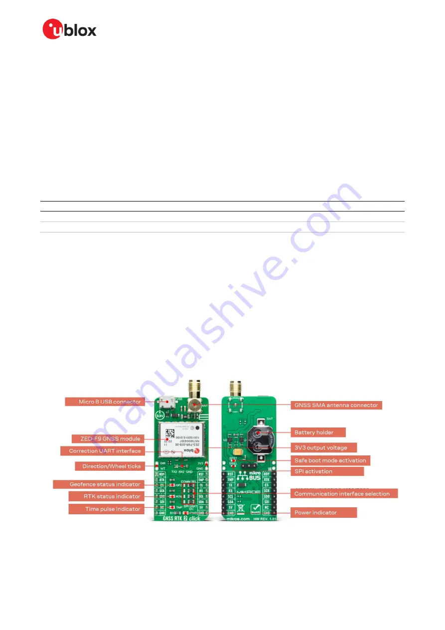
GNSS RTK 2
shows the GNSS RTK 2 Click board hosting the ZED-F9 GNSS module and other main
components.
Figure 20: MIKROE GNSS RTK 2 Click board


