LEXI-R422 - System integration manual
UBX-23007449 - R02
Design-in
Page 59 of 108
C1-Public
2.4.2
Cellular and GNSS RF coexistence
Overview
Desensitization or receiver blocking is a form of electromagnetic interference where a radio receiver
is unable to detect a weak signal that it might otherwise be able to receive when there is no
interference (see
). Good blocking performance is particularly important in the scenarios
where several radios of various forms are used in close proximity to each other.
0
-120
-60
1575
Frequency [MHz]
Power [dBm]
Filter gain [dB]
1800
2025
1350
1125
GNSS signal
LTE signal
Filter response
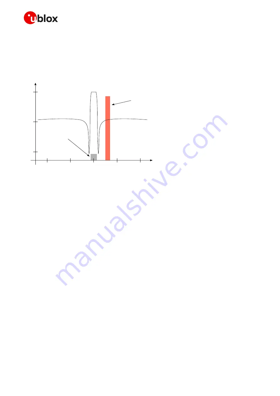
Figure 38: Interference due to transmission in LTE B3, B4 and B66 low channels (1710 MHz) adjacent to GNSS frequency
range (1561 to 1605 MHz). Harmonics due to transmission in LTE B13 high channels (787 MHz) may fall into the GNSS bands
Jamming signals may come from in-band and out-of-band frequency sources. In-band jamming is
caused by signals with frequencies falling within the GNSS frequency range, while the out-of-band
jamming is caused by very strong signals adjacent to the GNSS frequency range so that part of the
strong signal power may leak at the input of the GNSS receiver and/or block GNSS reception.
If not properly taken into consideration, in-band and out-band jamming signals may cause a reduction
in the carrier-to-noise power density ratio (C/No) of the GNSS satellites.
In-band interference
In-band interference signals are typically caused by harmonics from displays, switching converters,
micro-controllers and bus systems. Moreover, considering for example the LTE band 13 high channel
transmission frequency (787 MHz) and the GPS operating band (1575.42 MHz
±
1.023 MHz), the
second harmonic of the cellular signal is exactly within the GPS operating band. Therefore, depending
on the board layout and the transmit power, the highest channel of LTE band 13 is the channel that
has the greatest impact on the C/No reduction.
Countermeasures against in-band interference include:
•
Maintaining a good grounding concept in the design
•
Ensuring proper shielding of the different RF paths
•
Ensuring proper impedance matching of RF traces
•
Placing the GNSS antenna away from noise sources
•
Add a notch filter along the GNSS RF path, just after the antenna, at the frequency of the jammer


