


TFP480
Page 11 of 12
Care and
Maintenance
Before closing a fire protection system
control valve for inspection or mainte-
nance work on the fire protection sys-
tem that it controls, obtain permission
to shut down the effected fire protec-
tion system from the proper authorities
and notify all personnel who may be af-
fected by this action.
The following inspection/test proce-
dures will result in operation of the as-
sociated alarms. Notify the proper au-
thorities and advise those responsible
for monitoring proprietary and/or cen-
tral station alarms.
After placing a fire protection system
in service, notify proper authorities and
advise those responsible for monitor-
ing proprietary and/or central station
alarms.
The following inspection/test procedure
for the RAPID RESPONSE Model RCP-
1 Residential Control Panel must be
performed as indicated, in addition to
any specific requirements of the NFPA.
Any impairment must be immediately
corrected.
The owner responsible for the inspec-
tion, testing, and maintenance of their
fire protection system and devices in
compliance with this document, as
well as with the applicable standards
of the National Fire Protection Associa-
tion (e.g., NFPA 25), in addition to the
requirements of any authority having
jurisdiction. The installing contractor or
product manufacturer should be con-
tacted relative to any questions.
Automatic sprinkler systems are recom-
mended to be inspected, tested, and
maintained by a qualified Inspection
Service in accordance with local re-
quirements and/or national codes.
Inspection/Test Procedure
The Model RCP-1 Panel can be in-
spected and tested without having to
flow water into the system piping. The
inspection and testing, in accordance
with the requirements of NFPA 25, must
be performed annually.
General Inspection/Test
Step 1.
Verify the Air Pressure Gauge
indicates a system air pressure of 10
to 14 psi.
Step 2.
Verify the Operator Interface of
the Electronic Control only indicates a
green light for AC Power.
Step 3.
Open and then close the Flow
Test Valve. The Water Supply Gauge
should drop to a previously noted re-
sidual pressure and then return to the
normal static pressure.
Step 4.
Perform a lamp test by press-
ing and holding the ACCEPT SIGNAL
KEY for a duration of five seconds. Ver-
ify that all system LEDs are functioning.
Trip Test
Step 1.
Close the System Control Valve
and accept the supervisory alarm at the
Operator Interface by pressing the AC-
CEPT SIGNAL KEY.
Step 2.
Partially open the Drain Valve
to relieve air pressure. When the sys-
tem trips (releases), completely open
the Drain Valve.
•
Note that the Operator Interface
IDC1 indicates alarm when the air
pressure gauge indicates nominal-
ly 8 psi.
•
Note that the Operator Interface indi-
cates system released.
•
Note that water is discharging from
the drain line.
Step 3.
Reset the Model RCP-1 Pan-
el following the appropriate resetting
instructions.
SYSTEM PROGRAMMING MODE
Check
If a malfunction of the Electronic Con-
trol is suspected, verify the pre-pro-
gramming of the panel as follows:
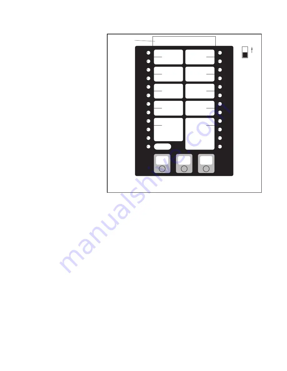
Step 1.
With reference to Figure 8, re-
move the Operator Interface card and
reinsert it so that the SYSTEM PRO-
GRAMMING MODE information listed
on the card’s back side faces front.
Step 2.
Place the PROGRAM SWITCH
(Figure 8) to the ON position and then
momentarily press the ACCEPT SIG-
NAL KEY to accept the resulting pro-
gramming mode trouble.
Step 3.
Press the ACCEPT SIG-
NAL KEY to scroll through MODES 1
through 10 and verify that the POSI-
TION 1 through 10 lights up as follows:
•
MODE 1: POSITION 6 for Dry Pipe
•
MODE 1/3: POSITION 1
•
MODE 2: POSITION 1 for Class B Ini-
tiating Circuit Style
•
MODE 3: POSITION 1 for 0-Second
Automatic Time Release Delay
•
MODE 4: POSITION 1 for No RAC
Cutout Timer
•
MODE 5: POSITION 1 for 0 Second
Manual Release Time Delay
•
MODE 6: POSITION 1 for Immediate
Abort Release Time Delay
•
MODE 7: POSITION 1 for Temporal
NAC Coding
SYSTEM PROGRAMMING MODE
ACCEPT
SIGNAL
MODE 10
MODE 9
MODE 8
MODE 7
MODE 6
MODE 5
MODE 4
MODE 3
MODE 1
MODE 2
SIGNAL
SILENCE
SYSTEM
RESET
POSITION 10
POSITION 9
POSITION 7
POSITION 8
POSITION 6
POSITION 5
POSITION 4
POSITION 3
POSITION 1
POSITION 2
INTERFACE
CARD
ON
PROGRAM
SWITCH
FIGURE 8
OPERATOR INTERFACE CARD (BACK SIDE)
SYSTEM PROGRAMMING MODE


