


Diagnostic Screens
iSTAR eX Installation and Configuration Guide
6–13
To configure a HyperTerminal session
1. Connect the RS-232 diagnostic port (J4) on the iSTAR eX GCM to the
Comm port on a computer with HyperTerminal software.
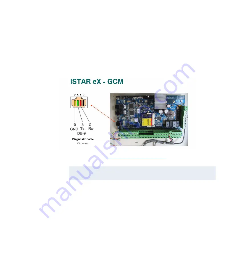
2. Use a cable with a DB9 female connector on one end and an RJ25 or RJ14
on the other end to connect the iSTAR eX to the Comm port.
3. Wire the cable as shown in Figure 6.9.
Figure 6.9: Diagnostic Cable
To display diagnostic messages using a HyperTerminal session:
1. Open a web browser, and enter the URL or IP address of the iSTAR eX
controller for which you want diagnostic information. The Diagnostic
Utility appears.
2. Select
SID Diagnostic Level
. The iSTAR Diagnostic Level Control page
appears.
3. Select the information you want to display for each component and click
Submit
.
NOTE
Set the Comm port to 115,200 baud, 8-bit, 1 stop bit, hardware flow
control.
Содержание iSTAR eX
Страница 12: ...Table of Contents xii iSTAR eX Installation and Configuration Guide...
Страница 58: ...Backup and Restore 1 38 iSTAR eX Installation and Configuration Guide...
Страница 146: ...Starting the ICU 5 12 iSTAR eX Installation and Configuration Guide Figure 5 4 ICU Main Window...
Страница 176: ...Downloading Firmware Updates 5 42 iSTAR eX Installation and Configuration Guide Figure 5 19 Monitor Station Controllers...
Страница 200: ...STAR eX Diagnostic Tests 7 10 iSTAR eX Installation and Configuration Guide...
Страница 210: ...A 10 iSTAR eX Installation and Configuration Guide One Wire A B C Figure A 6 One Wire A B C LED control...
Страница 212: ...A 12 iSTAR eX Installation and Configuration Guide...


