Tomcat i915 S5120
Chapter 2: Board Installation
2-13
http://www.tyan.com
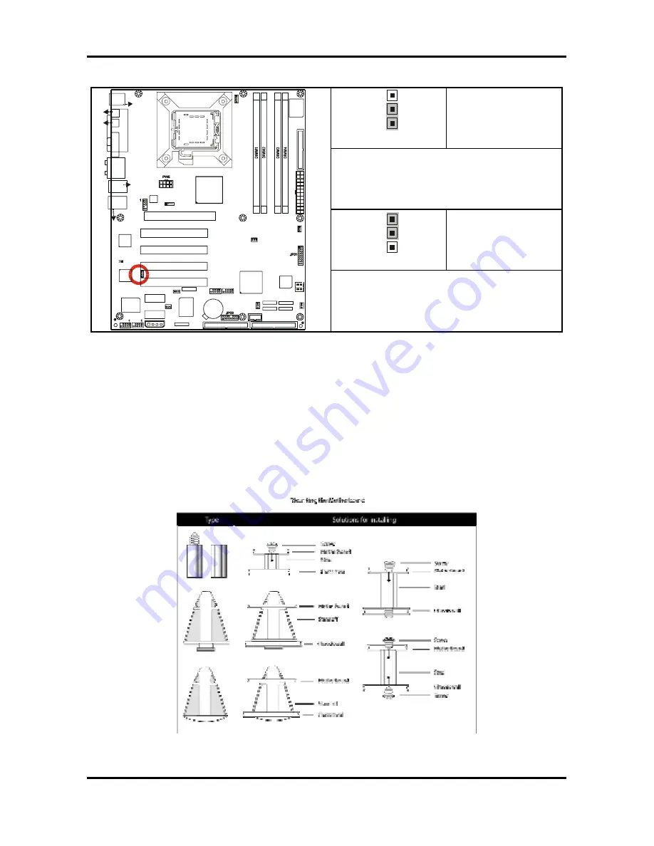
2.5.15 10/100 LAN (Intel 82551QM) Enable/Disable Jumper: JP23
(optional)
3
1
Pin 1 – 2 Closed
(Default)
To enable on-board 10/100 Ethernet
3
1
Pin 2 – 3 Closed
USB3
1
1
1
1
J8
(KB+Mouse)
J30
J15 (
VG
A)
J6
(P
ar
allel P
or
t)
FAN2
JP3
PW8
LAN+
USB2
J33
(Audio)
ALC880
PFAN
JP1
BIOS
JP19
Intel
i915G
Intel
ICH6
32-bit 33MHz (5V) PCI PCI2
32-bit 33MHz (5V) PCI PCI3
32-bit 33MHz (5V) PCI PCI4
PCI-E2
SATA2
SATA1
FD
D
1 J7
JP15
RAID-IDE1 JP4 (Optional)
IDE1 J11
1
x16 PCI Express PCI-E1
SUPER
I/O
BT1
PCI-E3
USB4
1
VIA
VT6307
LED1
32-bit 33MHz (5V)PCI PCI1
SATA3
SATA4
FAN4
Promise
PDC20579
(Optional)
JP8
1
JP9
BROADCOM
LAN
(Optional)
1
JP2
FAN1
LAN+
USB1
J22
COM1
JP18
1
1
JP13
JP5
JP6
PW3
1
FAN3
JP20
J27
J25
J24
J26
J23
S5120
J31
(S
PD
IF
-IN
)
(S
PD
IF
-O
U
T)
KB(Bottom )
Mouse(Top)
USB (Bottom)
10/100 LAN (Top)
(Optional)
USB (Bottom)
GbE LAN (Top)
J28
JP10
JP11
Intel
LAN
1
JP23
1
To disable on-board 10/100 Ethernet
2.6 Mounting the Motherboard
Before installing your motherboard, ensure that your chassis is fully compatible. The Tomcat
i915 S5120 motherboard conforms fully to the ATX specification. Your chassis should include
preinstalled mounting posts that match exactly with the mounting holes in the motherboard.
Lay the motherboard on top of the mounting holes to ensure that all the necessary mounting
posts exist in your chassis and that they match the mounting holes on the motherboard.
Some chassis’ include plastic studs instead of metal. Although the plastic studs are usable,
TYAN recommends using metal studs with screws that will fasten the motherboard more
securely in place.
See the diagram below for some examples of typical motherboard fixing studs.
TIP:
Use metal studs if possible, as they hold the motherboard into place more securely than
plastic standoffs.


