background image

ULTRAFEED VAF-4 

7-2                                                                                          ASSEMBLY PROCEDURE                                                               Manual 0-5332

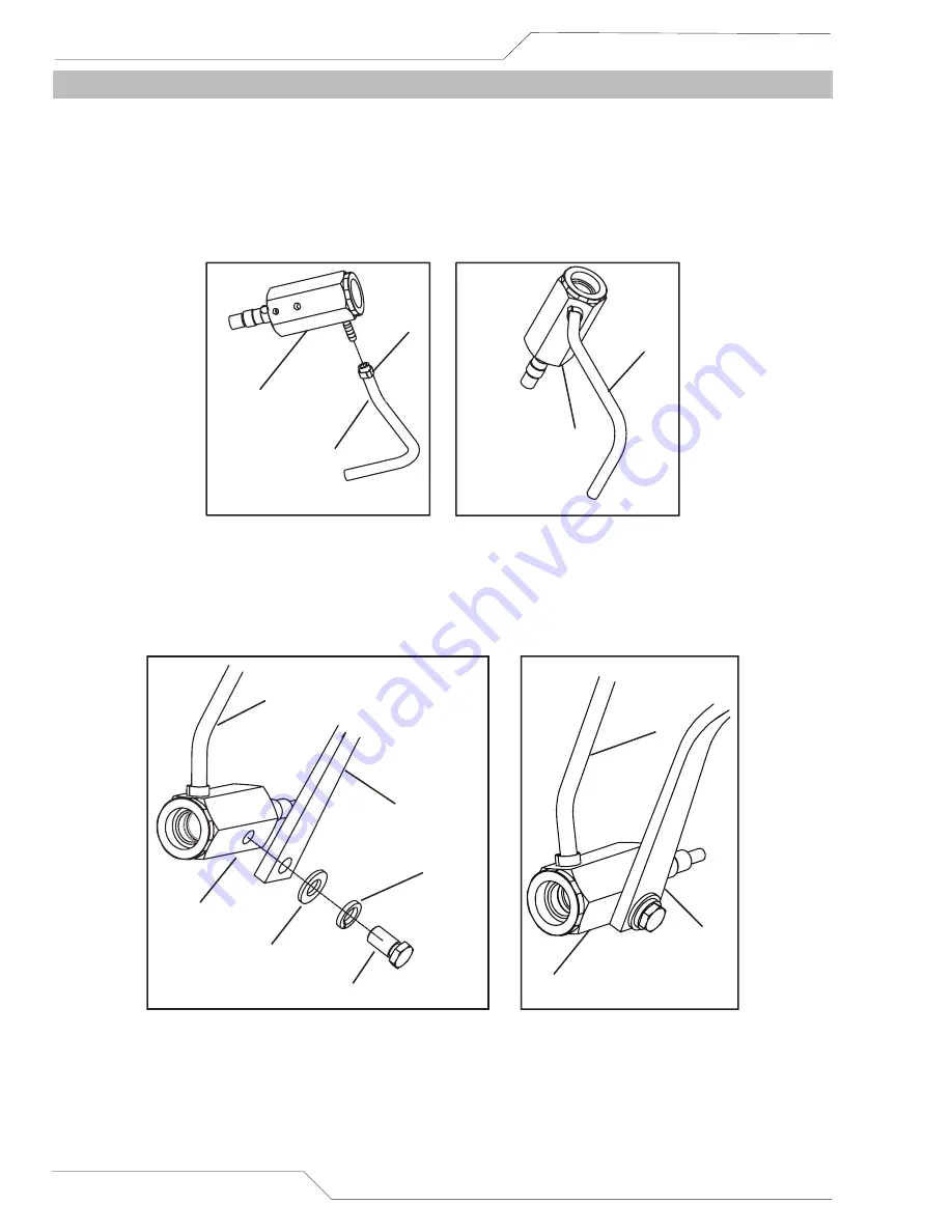
7.02  Installing Tweco No. 4 Adaptor

1.  Reconnect the gas hose.

a. Place the hose clamp over gas hose.
b. Push the gas hose onto the Tweco No. 4 Gun Adaptor gas inlet.
c. Slide the hose clamp forward until it sits approximately 5mm from the end of the gas hose.
d. Tighten the hose clamp with a suitable crimping tool.

Gun Adaptor, 

Tweco No. 4

Hose Clamp

Gas Hose

Gun Adaptor, 

Tweco No. 4

Gas Hose

Art # A-12820

Figure 7-2 Reconnecting Gas Hose

2.  Reconnect the welding cable.

a.  Attach the welding cable lug to Tweco No. 4 Adaptor, using the M10 Flat Washer, M10 Spring Washer and 

M10 × 18 Hex Bolt.

Welding Cable

Flat Washer, M10

Spring Washer, M10

Hex Bolt, M10 × 18

Art # A-12821

Welding Cable

Gun Adaptor, 

Tweco No. 4

Gun Adaptor, 

Tweco No. 4

Gas Hose

Gas Hose

Figure 7-3 Reconnecting Welding Cable

Содержание ULTRAFEED VAF-4

Страница 1: ...Tweco com Art A 12466_AB ULTRAFEED VAF 4 Wirefeeder Service Manual English Revision AA Issue Date March 27 2015 Manual No 0 5332...

Страница 2: ...tinguish ourselves from our competition through market leading innovation and truly dependable products that will stand the test of time We strive to enhance your productivity efficiency and welding p...

Страница 3: ...victortechnologies com Copyright 2015 by Victor Technologies International Inc All rights reserved Reproduction of this work in whole or in part without written permission of the publisher is prohibit...

Страница 4: ...3 3 3 05 Ventilation 3 3 3 06 Mains Supply Voltage Requirements 3 3 3 07 Electromagnetic Compatibility 3 3 SECTION 4 operation 4 1 4 01 Front Panel Controls Indicators and Features 4 1 4 02 Rear Pane...

Страница 5: ...10 Preliminary Check of the Power Supplies Main Power ON 5 13 5 11 PCB Connectors 5 15 5 12 Main Circuit Description 5 19 SECTION 6 disassembly procedure 6 1 6 01 Safety Precautions for Disassembly 6...

Страница 6: ...cation 8 1 8 02 How To Use This Parts List 8 1 8 03 Replacement Parts without wirefeed plate 8 2 8 04 Replacement Parts Wirefeed Plate 8 4 Appendix 1 options and accessories A 1 Appendix 2 connection...

Страница 7: ...round the workpiece to a good electrical earth ground 11 Do not touch electrode while in contact with the work ground circuit 12 Use only well maintained equipment Repair or replace damaged parts at o...

Страница 8: ...the American Welding Society AWS Miami Florida Guide for Shade Numbers Process Electrode Size in mm Arc Current Amperes Minimum Protective Shade Suggested Shade No Comfort Shielded Metal Arc Welding...

Страница 9: ...ft 10 7 m of the welding arc If this is not possible tightly cover them with approved covers 4 Be alert that welding sparks and hot materials from welding can easily go through small cracks and openin...

Страница 10: ...ans rotors and belts can cut fingers and hands and catch loose clothing 1 Keep all doors panels covers and guards closed and securely in place 2 Stop engine before installing or connecting unit 3 Have...

Страница 11: ...the body 4 Keep welding Power Source and cables as far away from body as practical ABOUT PACEMAKERS The above procedures are among those also normally recommended for pacemaker wearers Consult your d...

Страница 12: ...ure regulation equipment Deviation from the following safety and operation instructions can result in fire explosion damage to equipment or injury to the operator E Compressed Gas Cylinders The Depart...

Страница 13: ...I Standard Z49 1 from American Welding Society 550 N W LeJeune Rd Miami FL 33126 Safety and Health Standards OSHA 29 CFR 1910 from Superintendent of Documents U S Government Printing Office Washington...

Страница 14: ...ositive Direct Current DC Protective Earth Ground Line Line Connection Auxiliary Power Receptacle Rating Auxiliary Power Art A 04130_AB 115V 15A t t1 t2 X IPM MPM t V Fuse Wire Feed Function Wire Feed...

Страница 15: ...N ET D ESSAI 1 06 Dangers relatifs au soudage l arc AVERTISSEMENT L ELECTROCUTION PEUT ETRE MORTELLE Une d charge lectrique peut tuer ou br ler gravement L lectrode et le circuit de soudage sont sous...

Страница 16: ...e AWS F2 2 2001 R2010 Modifi avec l accord de l American Welding Society AWS Miami Florida Guide de teinte des lentilles Proc d Taille de l lectrode en mm po Courant d arc amp res Gamme d intensit min...

Страница 17: ...pantalon revers des bottines de s curit et un casque 2 Portez des lunettes de s curit approuv es Des crans lat raux sont recommand s 3 Entourez l aire de soudage de rideaux ou de cloisons pour prot ge...

Страница 18: ...s pi ces connexes doivent tre maintenus en bon tat 6 Ne placez pas le visage face l ouverture du robinet de la bouteille lors de son ouverture 7 Laissez en place le chapeau de bouteille sauf si en uti...

Страница 19: ...LIQUIDE DE REFROID ISSEMENT BRULANT SOUS PRESSION PEUVENT BRULER LA PEAU ET LES YEUX Le liquide de refroidissement d un radiateur peut tre br lant et sous pression 1 N tez pas le bouchon de radiateur...

Страница 20: ...Si vous ne pouvez pas les enlever prot gez les avec une cou vre ignifuge AVERTISSEMENT N effectuez JAMAIS d op rations de soudage sur un r cipient qui a contenu des liquides ou vapeurs toxiques combus...

Страница 21: ...ation CGAP 1 Manipulations curis edesgazcompri m s en conteneur pour plus d informations sur l utilisationetlamanutentiondesbouteilles AVIS Ce document CGA p t peut tre obtenu en crivant Compressed Ga...

Страница 22: ...Rd Miami FL 33128 National Electrical Code norme 70 NFPA National Fire Protection Association Batterymarch Park Quincy MA 02269 Safe Handling of Compressed Gases in Cylinders docu ment P 1 Compressed...

Страница 23: ...Continue DC Terre de Protection Ligne Connexion de la Ligne Source Auxiliaire Classement de Prise Source Auxiliaire Art A 07639_AB 115V 15A t t1 t2 X IPM MPM t Fusible D roulement du Fil Alimentation...

Страница 24: ...ce continues to be examined Until the final conclusions of the research are reached you may wish to minimize your exposure to electromagnetic fields when welding or cutting To reduce magnetic fields i...

Страница 25: ...d above along with a full description of the parts in error Move the equipment to the installation site before un crating the unit Use care to avoid damaging the equip ment when using bars hammers etc...

Страница 26: ...tained herein when installed operated maintained and repaired in accordance with the instructions provided This equipment must be checked periodically Defective equipment including welding leads shoul...

Страница 27: ...To explain the 10 minute duty cycle period the following example is used Suppose the wire feeder is designed to operated at 60 duty cycle 450 amperes This means that it has been designed and built to...

Страница 28: ...terconnection Plug 19pin Wire Sizes Solid 023 1 16 6mm 1 6mm Aluminium 035 1 16 0 9 mm 1 6 mm Flux Cored 030 5 64 0 8 mm 2 0 mm Maximum Wire Spool Weight 60 lb 27kg Table 3 1 Ultrafeed VAF 4 Specifica...

Страница 29: ...er informa tion please refer to IEC 60529 G Precautions must be taken against the Wire Feeder toppling over The Wire Feeder must be located on a suitable horizontal surface in the upright position whe...

Страница 30: ...ing Power Source enclosure 2 Maintenance of Welding Equipment The welding equipment should be routinely maintained according to the manufacturer s recommendations All access and service doors and cove...

Страница 31: ...er to Sec tions 4 24 4 25 5 01 or 5 02 for further information If the Fault indicator is flashing while welding refer to Section 4 25 as the motor overload protection is active 3 AMPS Indicator The re...

Страница 32: ...y turning the knob counter clockwise The value may also be adjusted while a weld is in progress if this occurs the right display will briefly switch to show the adjusted value as the knob is turned an...

Страница 33: ...digital meter is used to display the pre set preview Voltage in MIG mode and actual welding voltage of the power source or simply when the VAF 4 is connected to a power source without a control signal...

Страница 34: ...ress and release the SCH 1 SCH 2 button to select either SCH 1 or SCH 2 the red indicator will illuminate to identify which Schedule is selected 12 INCH Button After turning the power ON press this bu...

Страница 35: ...emote control potentiometer 7 Wiper arm connection to 5k ohm remote control Wirespeed MIG mode potentiometer 8 Wiper arm connection to 5k ohm remote control Volts MIG mode potentiometer Table 4 1 Pin...

Страница 36: ...protects the Wirefeeder from electrical faults on the 115VAC circuit In the event of a fault occuring this circuit breaker will trip pop out A short cooling period must be allowed before an attempt is...

Страница 37: ...o select local panel control on the Wirefeeder or remote control from the 8 pin remote control socket on the front of the Wirefeeder Default Local Remote Local Local Remote If MIG Remote is selected b...

Страница 38: ...the amount of MIG wire that protrudes from the MIG gun after the completion of MIG welding commonly referred to as stick out Default Burn Back 0 15 sec note Gun should be kept in position until Burn...

Страница 39: ...his is used to weld two thin plates together by melting the top bottom plates together to form a nugget between them The weld time is set by the Spot Time Default Spot Time 2 0 sec 0 1 to 20 0 seconds...

Страница 40: ...e user to select what is shown on the LEFT Display when welding With some power sources it may not be possible to display welding amps on the VAF 4 display when welding in this case set the display to...

Страница 41: ...required to use a Power Source that is not on Table 4 6 the VAF 4 Wirefeeder can be set up manually to interface with most Power Sources Refer to Subsection 4 04 Some information about this power sour...

Страница 42: ...MIN setting and advance to the next menu item Advanced Feature Left Display Feature Description Right Display Parameter Selection Display Volts Maximum The LEFT DISPLAY will now show VDSP MAX Adjust t...

Страница 43: ...FT KNOB clockwise to save the VSET MAX setting and advance to the next menu item Advanced Feature Left Display Feature Description Right Display Parameter Selection Save User Set The LEFT DISPLAY will...

Страница 44: ...15 Crater CRAT OFF Only in 4T Mode Crater Volts CRAT VOLT 70 Only when in 4T Mode and Crater is ON Crater Wirefeed Speed CRAT WFS 70 Only when in 4T Mode and Crater is ON Spot Time SPOT TIME 2 0 Only...

Страница 45: ...being used Display PCB Art A 12469 DIP Switch Figure 4 6 DIP Switch on Display PCB S3S4S5 Vmin Vmax Vsetmin J L Vsetmax J L Welder S3 Off 0 S4 On 1 S5 On 1 10 36 2 3 8 17 ArcMaster 401MST default Arc...

Страница 46: ...ully clockwise to lock the plug into position 2 Fit the Tweco No 4 MIG Gun to the Wirefeeder by pushing the MIG Gun Connector into the Tweco No 4 GUN Adaptor and secure it by tightening the Thumb Scre...

Страница 47: ...59 N m 4 Spring Washer M10 with torque 45 59 N m 2 Nut M10 with torque 45 59 N m 2 Table 4 7 Handle Assembly Install the handle assembly as below Secure the handle assembly to the base assembly with M...

Страница 48: ...ashers M10 Spring Washers and M10 Nuts with 17mm wrench that secure the handle assembly and remove the handle assembly and fixings from the base assembly Refer to Figure 4 8 2 Use 14mm wrench to secur...

Страница 49: ...ents are included in this kit Item Description Quantity 1 Bolt M12 x 30 2 2 Star Washer M12 2 3 Flat Washer M12 2 4 Screw Countersunk M5 x 12 2 5 Spool Cover Mounting Bracket 1 6 Spool Cover 1 7 Spool...

Страница 50: ...asher small hole 3 lobe Screw Retaining Clip Art A 12476_AB Figure 4 13 Removing Spool Hub Assembly 2 Assemble the Spool Cover Mounting Brackets one inside and one outside the spool cover with the two...

Страница 51: ...nce Friction Washer Spool Hub Keyed Washer Spring Flat Washer 3 lobe Screw Retaining Clip Art A 12478 Figure 4 15 Spool Hub Assembly Warning Fully tighten all fasteners Refer to the figures below for...

Страница 52: ...7 The bottom hole is for installing a spool of 8 diameter As delivered from the factory the unit has the spool hub fitted into the middle 12 spool position 1 Remove the retaining clip from the spool h...

Страница 53: ...result in the wire spool circumference continuing no further than 3 4 after release of the trigger The electrode wire should be slack without becoming dislodged from wire spool Please refer to Figure...

Страница 54: ...Swing the Pressure Adjusting Knobs back into place 6 Use the Pressure Adjusting Knobs to create a snug condition Clockwise to tighten and Counter Clockwise to loosen 7 Turn ON the power supply Set pr...

Страница 55: ...sitioning Pins and install the Feed Roll Washer and Screw 5 Tighten the screw clockwise 6 Lower the Pressure Roll Arm 7 Swing the Pressure Adjusting Knob back into place 8 Use the Pressure Adjusting K...

Страница 56: ...s It is the user s re sponsibility to prevent such conditions Before handing or using the equipment understand and comply at all times with the safe practices prescribed in this instruction SPECIFIC P...

Страница 57: ...OUTLET CONNECTION PRESSURE ADJUSTING SCREW Art A 12126 Figure 4 21 Fit Regulator Flowmeter to Cylinder Installation 1 Remove cylinder valve plastic dust seal Clean the cylinder valve outlet of impurit...

Страница 58: ...ion adjust working flow rate as follows 1 Slowly turn adjusting screw knob in clockwise direction until the outlet gauge indicates the required flow rate NOTE It may be necessary to re check the shiel...

Страница 59: ...herwise securely fixed in an upright position D Select MIG mode with the process selection control button Wirefeeder Connections A Connect the welding power cable from the Wirefeeder s interconnection...

Страница 60: ...re through the gun WARNING If the Gun Trigger is used to feed wire through the gun the electrode wire will be at welding voltage potential while it is being fed through the Wirefeeder system WARNING B...

Страница 61: ...ctrode wire manufacturer Welding current flows from the Power Source via dinse terminals It is essential however that the male plug is inserted and turned securely to achieve a sound electrical connec...

Страница 62: ...rough the Wirefeeder system WARNING Before connecting the work clamp to the work piece make sure the mains power supply is switched off Connection to ArcMaster 401MST Positive Welding Terminal Work Le...

Страница 63: ...ne s eyes flash or skin burn 6 Adjust the voltage of the power source to the desired value The gun switch must be triggered to close power source contactor WARNING In wire welding the welding wire wir...

Страница 64: ...Preflow Run In Ramp Postflow Gun Trigger Arc Established Gas Contactor Wire feed Burnback Art A 11262_AB Figure 4 26 Welding 2T Operation 4 20 Spot Operation Position the welding gun above the workpi...

Страница 65: ...e user can independently control the amount of crater filler time by adjusting the amount of time the gun switch is depressed Burnback Postflow Gun Trigger Arc Established Gas Contactor Wire feed Pref...

Страница 66: ...piece and depress the gun switch trigger Depressing the gun switch trigger enables the gas valve When preflow ends wire feed motor and power source are enabled the welding process begins Release the g...

Страница 67: ...rcuit This protection circuit is activated when ever excessive current flow in the protective earth ground is detected If the ground fault protection circuit is activated the yellow FAULT indicator on...

Страница 68: ...ULTRAFEED VAF 4 4 38 OPERATION Manual 0 5332 Notes...

Страница 69: ...G Gun liner or spool hub tension too tight or wire melted to tip or problem with wire spool etc 1 Defective motor Turn OFF Wire feeder then check motor feed mechanism can rotate 2 Defective Motor Cont...

Страница 70: ...gnal 19 pin connector Pin M to L ARC ESTABLISHED 15VDC If the power source does not provide an Establish signal then override the arc establish signal refer to Section 4 18 ERR 08 Motor Control PCB1 s...

Страница 71: ...ided from the power supply via the 19pin connector Circuit Breaker s on rear panel is tripped pops out Refer to Subsection 4 02 for further detail Faulty 19 Pin control cable connecting power source a...

Страница 72: ...2 for 15VDC If voltage is not present follow signal back to P3 connector on PCB1 If no voltage on PCB1 P3 connector replace PCB1 If voltage is present jumper P3 Pin 1 to 2 If gas flows and motor turn...

Страница 73: ...r operates but wire does not feed A B C Pressure on feed rolls not correctly adjusted Incorrect feed rolls used Worn feed roll A B C Adjust pressure on feed rolls so that it will be set to a minimum p...

Страница 74: ...panel Set MIG Control mode to local OR If a remote control device is fitted to the 8 pin remote control socket then the remote control device is faulty Repair or replace as necessary 15 Crater does n...

Страница 75: ...llow FAULT light is on A B C D E F G H I ERR 01 Ground Fault Current is flowing in the interconnection earth wire This may be a fault from 110VAC to frame or from weld output to frame ERR 03 Motor Cur...

Страница 76: ...as system causing solenoid to stay open or closed Faulty Motor Control CPB1 A B C D Check solenoid wiring header is plugged securely into Motor Control PCB1 Keep trigger switch ON measure the voltage...

Страница 77: ...tal Multimeter Screwdriver and spanner CRO 20 Mhz bandwidth isolating transformer 5 06 Visually Inspect Visually inspect the inside of the Wirefeeder The levels of current present in these units can c...

Страница 78: ...ry Check of the Motor Control PCB1 DC Bus Testing Multimeter Lead Placement Voltage with Supply voltage OFF Main capacitor bank Positive meter lead to TP 1 Negative meter lead to TP 2 5 VDC Table 5 4...

Страница 79: ...er Lead Placement Diode Voltage Switch ON Positive meter lead to TP 15 Negative meter lead to TP 16 0 to 1 W Switch ON Positive meter lead to TP 17 Negative meter lead to TP 18 0 to 1 W Switch OFF Pos...

Страница 80: ...eter lead to testpoint DC POS 0 2 0 8 VDC AC1 to DC NEG Positive meter lead to testpoint DC NEG Negative meter lead to testpoint AC1 0 2 0 8 VDC AC2 to DC NEG Positive meter lead to testpoint DC NEG N...

Страница 81: ...n Control Microprocessor is running is to look at the HEART BEAT LED This will flash slowly if the microprocessor is running If this is not flashing there is a problem with PCB1 and it will need to be...

Страница 82: ...r lead to TP 9 Negative meter lead to TP 10 15 0 5 VDC Motor Drive 15VDC supply Positive meter lead to TP 11 Negative meter lead to TP 10 15 0 5 VDC Main 5VDC supply Positive meter lead to TP 12 Negat...

Страница 83: ...Main 3 3VDC supply Positive meter lead to TP 22 Negative meter lead to TP 20 3 3 0 1 VDC Table 5 9 Display PCB2 Power Supplies Multimeter set to measure Voltage 5 11 PCB Connectors 1 Motor Control PCB...

Страница 84: ...A trigger output relay contact closed when triggered 3 No connection 4 No connection 5 19 pin J control output to Power Source 0 12 VDC 6 19 pin L control 0V 0 VDC 7 19 pin C weld volts signal from P...

Страница 85: ...mote control WireFeed Speed 5k W pot wiper 0 15 VDC 8 8 pin 8 Remote control Voltage 5k W pot wiper 0 15 VDC Table 5 15 P6 Header pin function connects to 8 pin remote control socket M M Terminals Pin...

Страница 86: ...Art A 12023 Figure 5 8 Display PCB2 Connectors P1 Header Pin Pin function Signal 1 15V 15 VDC 2 0V 0 VDC 3 Can Bus high signal 5 VDC pk 4 Can Bus low signal 5 VDC pk 5 Can Bus shield 0 VDC Table 5 18...

Страница 87: ...rs The 110VAC supply uses one pole of the double pole switch the 4A circuit breaker and connects through to recti fier BR1 The 42VAC supply uses the other pole of the double pole switch the 8A circuit...

Страница 88: ...the Motor Control PCB1 The motor negative is connected to P11 on the Motor Control PCB1 Art A 12025 Figure 5 10 Control Circuit The main DC bus is filtered by E4 E5 and E6 From this a flyback converte...

Страница 89: ...332 DISASSEMBLY PROCEDURE 6 1 SECTION 6 disassembly procedure 6 01 Safety Precautions for Disassembly NOTE Read and follow safety information in Section 5 04 before proceeding Unplug unit before begin...

Страница 90: ...SASSEMBLY PROCEDURE Manual 0 5332 6 02 Cover Panel Removal 1 Remove the ten screws M5 1 4 13 securing the Cover Panel 2 Disconnect the Earth Wire connected to the Cover Panel 2 Art A 12815 1 Figure 6...

Страница 91: ...03 Front Panel Removal 1 Remove the two screws M6 16 securing the Front Panel 2 Disconnect the Cable Assembly connecting Display PCB2 and Motor Control PCB1 3 Disconnect the Earth Wire from the Front...

Страница 92: ...D VAF 4 6 4 DISASSEMBLY PROCEDURE Manual 0 5332 6 04 Display PCB2 Removal 1 Remove the four screws M4 8 securing the Display PCB2 2 Disconnect P1 connector 1 Art A 11606_AB 2 Figure 6 3 Removing Displ...

Страница 93: ...Disconnect P2 Head Pin from Motor Control PCB1 4 Disconnect P6 Head Pin from Motor Control PCB1 5 Disconnect P5 Head Pin from Motor Control PCB1 6 Disconnect P3 Head Pin from Motor Control PCB1 7 Disc...

Страница 94: ...RE Manual 0 5332 6 06 Main Input Rectifier Removal 1 Disconnect the terminals connected to the Main Input Rectifier 2 Remove the two screws M4 20 securing the Main Input Rectifier 1 2 1 Art A 11608 Fi...

Страница 95: ...Disconnect the terminals connected to the Main ON OFF Switch 2 Push the Main ON OFF Switch forward and remove it 3 Disconnect the terminals connected to the Circuit Breaker 4 Unscrew the plastic cap...

Страница 96: ...6 08 Gas Valve Removal 1 Remove the two screws M4 8 securing the Gas Valve 2 Remove the two hose clamps over the gas hose and disconnect the gas hose 3 Disconnect the two terminals connected to the Ga...

Страница 97: ...sconnect the gas hose from the Adaptor 2 Disconnect the welding cable from the Adaptor 3 Remove the M10 lock washer and M10 lock nut securing Tweco No 4 Adaptor 4 Remove the thumb screw and the M6 6 s...

Страница 98: ...the screw M5 12 and remove the Earth Wire connected to Division Plate 3 Remove the screw M5 1 4 13 securing Division Plate 4 Remove the two screws M6 30 and remove the Division Plate and Wirefeed Pla...

Страница 99: ...TRAFEED VAF 4 Manual 0 5332 DISASSEMBLY PROCEDURE 6 11 6 11 Base Panel Removal 1 Remove the four screws M8 30 securing Base Panel and remove the Base Panel 1 Art A 11613 Figure 6 10 Removing Base Pane...

Страница 100: ...ULTRAFEED VAF 4 6 12 DISASSEMBLY PROCEDURE Manual 0 5332 Notes...

Страница 101: ...AFEED VAF 4 Manual 0 5332 ASSEMBLY PROCEDURE 7 1 SECTION 7 assembly procedure 7 01 Installing Base Panel 1 Install the four screws M8 30 securing Base Panel 1 Art A 11613 Figure 7 1 Installing Base Pa...

Страница 102: ...hten the hose clamp with a suitable crimping tool Gun Adaptor Tweco No 4 Hose Clamp Gas Hose Gun Adaptor Tweco No 4 Gas Hose Art A 12820 Figure 7 2 Reconnecting Gas Hose 2 Reconnect the welding cable...

Страница 103: ...asher and M10 Lock Nut over the threaded end of the Tweco No 4 Adaptor Tighten the M10 Lock Nut securely 4 Install the M6 6 set screw in the Wirefeed Plate and then install the thumb screw Art A 12822...

Страница 104: ...stall the two screws M6 30 and secure the Wirefeed Plate to the Base Panel 3 Install the screw M5 1 4 13 and secure the Division Plate to the Base Panel 4 Install the screw M5 12 and reconnect the Ear...

Страница 105: ...2 ASSEMBLY PROCEDURE 7 5 7 04 Installing Gas Valve 1 Reconnect the two terminals to the Gas Valve 2 Reconnect the gas hose 3 Install the two screws M4 8 and secure the Gas Valve 3 2 1 Art A 11616 Figu...

Страница 106: ...uit Breakers 1 Push the Main ON OFF Switch forward 2 Reconnect the terminal to the Main ON OFF Switch 3 Place the Circuit Breaker and install the plastic caps to secure it 4 Reconnect the terminals to...

Страница 107: ...apply Heat Sink compound on the rear of Main Input Rectifiers 2 Install the two screws M4 20 with torque 0 912 1 277 ft lbs 1 236 1 731 Nm to secure the Main Input Rectifiers 3 Reconnect the terminals...

Страница 108: ...Motor Control PCB1 3 Reconnect P2 Head Pin to Motor Control PCB1 4 Reconnect P6 Head Pin to Motor Control PCB1 5 Reconnect P5 Head Pin to Motor Control PCB1 6 Reconnect P3 Head Pin to Motor Control PC...

Страница 109: ...the four screws M4 8 and secure Display PCB2 to Front Panel 2 Reconnect Cable Assembly connecting Display PCB2 and Motor Control PCB1 3 Reconnect the Earth Wire to the Front Panel 4 Install the two sc...

Страница 110: ...ASSEMBLY PROCEDURE Manual 0 5332 7 09 Installing Cover Panel 1 Install the ten screws M5 1 4 13 to secure the Cover Panel 2 Reconnect the Earth Wire to the Cover Panel 2 Art A 12815 1 Figure 7 11 Ins...

Страница 111: ...How To Use This Parts List The Parts List is a combination of an illustration Figure Number and a corresponding list of parts which contains a breakdown of the equipment into assemblies subassemblies...

Страница 112: ...Socket 19 Pin Male Panel Mtg P1 W7005715 9 1 Socket Panel Dinse Male 50mm2 W7005716 10 1 SPOOL HUB ASSY W7005609 11 1 Wire Guide Outlet 0 8 1 2 WF W4017700 12 1 Adaptor Tweco No 4 W4017800 13 1 Handle...

Страница 113: ...ULTRAFEED VAF 4 Manual 0 5332 PARTS LIST 8 3 2 6 5 4 3 7 1 8 9 10 Art A 12485_AB 13 12 11 22 14 15 17 18 16 Figure 8 1 Replacement Parts without wirefeed plate...

Страница 114: ...14 1 Motor 42V WF W7005713 15 1 Wire Drive Assy 4R WF W7005707 16 1 Wire Guide Inlet 0 8 1 6 WF W7005710 17 1 Wire Guide Center 0 8 1 6 WF W7005711 18 2 Feed Roll Refer to Appendix 1 19 2 Idler Gear 4...

Страница 115: ...4 V groove knurled Flux Cored Table A 1 Feed Rolls NOTE NOTE 1 Two feed rolls are required for each wire size NOTE 2 indicates fitted as standard Other Accessories Accessories Part Number Description...

Страница 116: ...ULTRAFEED VAF 4 A 2 APPENDIX Manual 0 5332 Art A 12826 Appendix 2 connection diagram...

Страница 117: ...AL DAMAGES SUCH AS BUT NOT LIMITED TO LOST PROFITS AND BUSINESS INTER RUPTION The remedies of the Purchaser set forth herein are exclusive and the liability of Tweco with respect to any contract or an...

Страница 118: ...This Page Intentionally Blank...

Страница 119: ...ts No Labor Victor Professional Victor Technologies limited warranty shall not apply to Consumable Parts for MIG TIG Plasma welding Plasma cutting and Oxy fuel torches O rings fuses filters or other p...

Страница 120: ...aly Customer Care Ph 39 0236546801 Fax 39 0236546840 ASIA PACIFIC Cikarang Indonesia Customer Care Ph 6221 8990 6095 Fax 6221 8990 6096 Rawang Malaysia Customer Care Ph 603 6092 2988 Fax 603 6092 1085...

Отзывы: