Manual 2003 Rev D p/n 2003
18
05
Installation
Cooling Water Connections
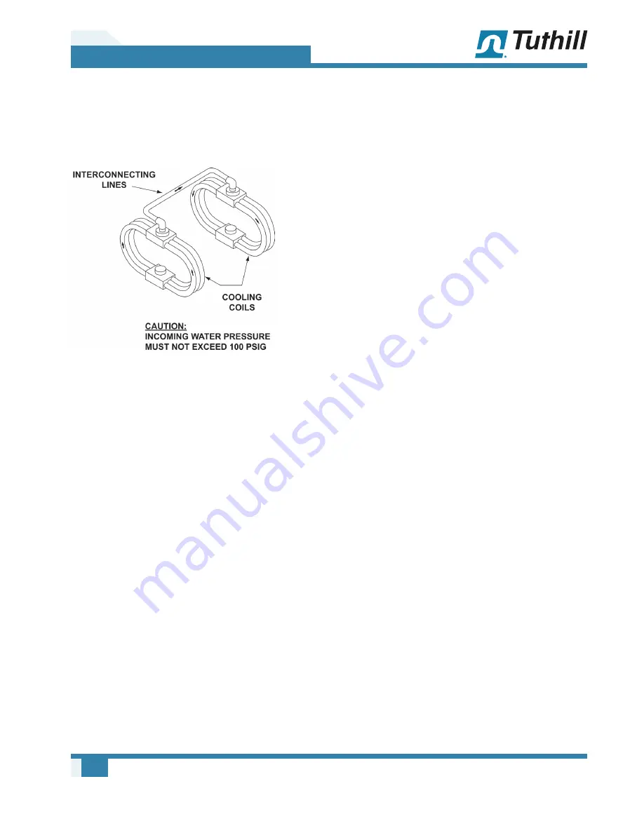
Cooling connection are on each end of the Booster.
One side will be the water in connection which will
cross over to the other end where the water out
connection will be used.
Figure 5-3 – Cooling Water Piping Harness
Cooling the oil sumps will prolong the life of the oil
and provide proper lubrication quality.
Provide an ON-OFF valve on the incoming line
and a regulating valve located in the drain line.
Terminate the drain line at an open drain for better
regulation of the water flow.
COOLING WATER SPECIFICATIONS
Boosters that will operate with continuous
discharge gas temperatures of 250°F (121°C) or
more must be connected to a water (liquid) supply
in order to maintain reasonable oil temperatures.
Generally a water flow of 1/2 to 1 GPM (1.9 – 3.8
L/min) is sufficient to maintain oil temperatures
below 150°F (65°C).
MOTOR DRIVES
Two drive connections commonly used are direct
drive and V-belt drive.
Direct Coupled
When installing the motor directly to the booster, align
the shafts to the coupling according to the coupling
manufacturer’s instructions. Boosters shipped with
motor directly coupled and mounted on a common
base have been aligned prior to shipment. Further
alignment is not normally necessary, but be sure
to check the alignment and make adjustments if
necessary prior to starting the booster.
Coupling halves must correctly fit the booster and
drive shafts so that only light tapping is required to
install each half. The two shafts must be accurately
aligned. A direct-coupled booster and motor must
be aligned with the two shafts.
Establish proper gap between coupling halves
according to the coupling manufacturer’s
instructions with the motor. Proper gap will minimize
the change for end thrust on the booster shaft.
V-Belts
If the motor and booster are V-belt connected,
the sheaves on both the motor and booster
shafts should be as close to the shaft bearings as
possible. Booster sheave is not more than 1/4 in.
(6.5 mm) from the booster drive end cover. Take
care should when installing sheaves on the booster
and motor shafts. Make sure the face is accurately
in line to minimize belt wear.
Adjust the belt tension to the to the manufacturer’s
specifications using a belt tension tester. Check
new belts for proper tension after 24 hours of run
time. When manufacturer data is not available,
industry guidelines recommend 1/64 in. deflection
for each inch of span (0.157 mm deflection per
centimeter of span) at 8 to 10 lb (3.6 – 4.5 kg) of
force in the center of the belt.
Insufficient tensioning is often indicated by slipping
(squealing) at start-up. Do not use belt dressing
on V-belts. Keep sheaves and V-belts free of oil
and grease. Remove tension from belts if the
drive is to be inactive for an extended period of
time. For more specific information, consult the
drive manufacturer. In a V-belt drive, the booster
sheave must fit its shaft accurately, run true, and
be mounted as close to the bearing housing as
possible to minimize bearing loads.


