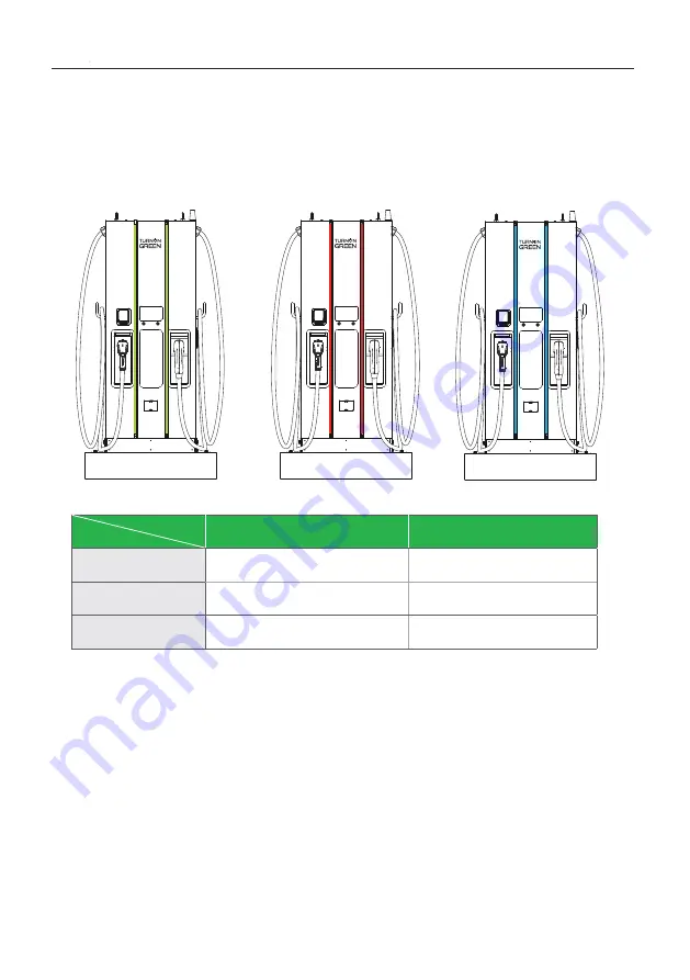
2.3 LED Indication and Operation Status
Left Indicator
Right Indicator
Standby
Green
Fault
Red
Charging
Blue
Status
LED
*Left LED for Left Connector, Right LED for Right Connector
7
Страница 1: ...FSP 600 60KW Standalone Fast Charger User Manual Installation Instructions Copyright 2021 TurnOnGreen Technologies a subsidary of TurnOnGreen Inc All Rights Reserved 84A99900206 RB1 FSP Series...
Страница 2: ......
Страница 3: ...ll sensor board for safely shutting down 12 3 4 Unpack the charger 15 3 5 Recommended Tools for Installation and Inspection 18 3 6 Installation Procedure 19 3 7 Installation Inspection Commissioning 2...
Страница 4: ...rging stations charging progress and billing information FSP 600 DC Fast Charger has a clear user inter face with function buttons safety certi cations and an excellent waterproof and dust proof desig...
Страница 5: ...tion Screen Right Button Left Button Credit Card Payment System Optional Charging Status Alarm information User Authorization Left DC Connector Right DC Connector The connectors installed on the EVSE...
Страница 6: ...UL Model CHAdeMO 150Vdc 500Vdc UL Model Maximum Output Current CCS UL Model 120A 150Vdc 500Vdc when output voltage up to 950Vdc the output current is 63A CHAdeMO UL Model 120A 150Vdc 500Vdc Maximum O...
Страница 7: ...quency Band GSM B3 B8 Internal CAN RS485 Input Protection OVP OCP OPP UVP SPD Output Protection OCP OVP LVP OTP IMD Internal Protection OTP AC Contactor Detection DC Contactor Detection Fuse Detection...
Страница 8: ...afety UL2202 UL2231 EMI EMC FCC CFR Title 47 Part 15 Subpart B 2020 ANSI C63 4 2014 ICES 003 2020 Issue 7 Charging Interface CHAdeMO Ver 1 2 UL Model CCS DIN 70121 UL Model Mechanical Speci cations Di...
Страница 9: ...nector Right DC Connector FSP 600 J00 CHAdeMO FSP 600 J0U CHAdeMO CCS1 FSP 600 U00 CCS1 FSP 600 U0U CCS1 CCS1 0 none 1 IEC 62196 2 Type 1 SAE J1772 Plug 2 IEC 62196 2 Type 1 SAE J1772 Socket 3 IEC 621...
Страница 10: ...ndication and Operation Status Left Indicator Right Indicator Standby Green Green Fault Red Red Charging Blue Blue Status LED Standby Fault Charging Left LED for Left Connector Right LED for Right Con...
Страница 11: ...2 5 Direction of cooling Airflow Air Out Air In 2 4 Dimensions Main Size of Charger Unit mm 8 POWERING POSITIVE CHANGE...
Страница 12: ...d the PE of the power distribu tion are directly connected to the earth The PE of the charger equipment is isolat ed to the PE of power distribution to the earth The capacity of power supply should be...
Страница 13: ...ent CAUTION The disconnect switch for each ungrounded conductor of AC input shall be provided by installation contractor or technician in accordance with the National Electric Code ANSI NFPA 70 CAUTIO...
Страница 14: ...bar in the main breaker panel and Neutral connected to Ground at that point 480Vac Line to Line Three Phase CAUTION This is feed from Wye connection power grid the FSP 600 can connect to L1 L2 or L3...
Страница 15: ...f safely shutting down and isolating the upstream safety device to isolate all in coming electrical feeds to the charger 2 Function Block Diagram Door Sensor Signal TIll Sensor Sensor Board Upstream C...
Страница 16: ...n cut off the charger will be totally shut down then goes into off line status immediately it won t be recover remote ly only relies on service people to be presented on site c This board has self tes...
Страница 17: ...ase reference models 3VA9988 0BL33 220 250VADC For 60KW CE 3VA9978 0BL33 208 277Vac 220 250 Vdc For 60KW UL Schneider Shunt release reference models LV429387 208 277VAC 60Hz For 60KW CE UL 6 Wires Spe...
Страница 18: ...ile service is not standard included in the order 3 NOTICE The delivery truck unloads the pallet carrying the charger The movement of the charger to its nal location is the responsibility of the custo...
Страница 19: ...Remove the surrounding boards STEP 1 STEP 2 Remove the carton and packing cushion and lm 16 POWERING POSITIVE CHANGE...
Страница 20: ...ve these 4 pcs of xing M12 screws STEP 3 To use lifting eye bolts to move the EVSE please apply 6mm 1 4 inches diam eter steel wire rope to the four eye bolts as following picture STEP 4 6 0 0 m m 2 4...
Страница 21: ...L2 L3 N Inner Diameter 10 5mm 0 41 Outer Diameter 22mm 0 87 2 Ring Terminal for PE Inner Diameter 6 4mm 0 25 Outer Diameter 22mm 0 87 Crimping Pliers for Ring Terminal Wire Stripper Wire Cutters Cran...
Страница 22: ...x 331 x 1800 mm 27 6x13 0x315 4 inch Front side 600 mm 23 6 inch in order to operate dashboard Left and right side 350 mm 13 8 inch in order to open left and right door Backside 600 mm 23 6 inch in o...
Страница 23: ...ort axis 8 mm 0 32 in long axis according to screw holes of charger 4 To t this positioning requirement a steel plate xture be suggested Please create the xture by the following drawing or order this...
Страница 24: ...meter 22mm 0 87 The conductor cross sectional area of input power wires should be not less than 53 5mm 106 kcmil If internet is connected via Ethernet at least 1800mm 71 of the Ethernet cable must be...
Страница 25: ...ers on 4 pcs of M12 screw of concrete base 2 nuts for each screw to secure the chargers Then x the base cover in the accessory pack in charger base METHOD 1 3 6 3 Two Methods of Fixing FSP 600 Charger...
Страница 26: ...f remove the eye bolts on the top of the cabinet must assemble the waterproof plastic bolts in the accessory pack 3 6 4 Installing Cables 23 Cable gland plate is optional for cables underground instal...
Страница 27: ...er and torque number 60Kgf cm L1 L2 L3 N PE Pull AC power cables to power distribution box connect the Protective Earth wire Green Yellow to ground point of power distribution box Neutral should be sh...
Страница 28: ...eaker over than or equal to 150A NFB B curve Do Inspection as section 3 6 1 to 3 6 3 Turn on the power source and be ready for operational testing The power supply of the Standalone DC Fast Charger wi...
Страница 29: ...Drafty Dust Level Anti Vandalism Measures 3 7 2 External Infrastructure Readiness Check Item Status Remark Check Charger Levelness with Leveling Ruler 3 in Horizontal Key Lock of Cabinet Door Fixing S...
Страница 30: ...6 1 Screw torque requirement table 3 7 4 EVSE Check Power On Item Status Remark Screen On Acoustic Noise Screen Display Function Time Display Correctly Network Connection Quality Cooling Fans Operatio...
Страница 31: ...t off 3 7 6 EVSE Check Emergency stop check Item Status Remark User Authorization RFID User Authorization QR Code User Authorization Others Waiting Time of Connection Check Reading of Each Display Ite...
Страница 32: ...ccount Password login https 192 168 1 10 admin 1231231238 192 168 1 10 SET UPGRADE OTHER LANGUAGE System System Charging Network Backend SET Network Open web service browser type the IP address of cha...
Страница 33: ...e WiFiSsid WiFiPassword Set Step 4 Select Wi Fi Module Select Wi Fi modes and ll in SSID and Password according to your application if not required just keep default WARNING Due to the different envir...
Страница 34: ...de the cabinet Step 1 4 2 1 SIM Card Installation Insert 3G 4G Micro SIM Card in the tray ensure the gold contacts are facing down and the notch is located in the upper right corner Note the tray migh...
Страница 35: ...ANGUAGE TelcomApn 3G 4G Module TelcomChapPapId TelcomChapPapPwd Set 4 2 2 Setting and Enable 3G 4G Module Network 3G 4G Module to ll corresponding information into TelcomApn TelcomChapPapid and Telcom...
Страница 36: ...ce the time server connection Manual setting Laptop with RJ45 interface Connect RJ45 cable from Laptop to charger s RJ45 port Setup parameters in the Webservice Step 1 Before opening web browser pleas...
Страница 37: ...indow ap pears 192 168 1 10 SET UPGRADE OTHER LANGUAGE System System Charging Network Backend 192 168 1 10 System System Information Version Information 192 168 1 10 XXXX XX XX XX XX XX System Informa...
Страница 38: ...Messages 5 1 Operating Sequence When the charger is powered on it start with the Charging Station Initializing page You will see the below image on the screen after powering on and the system is initi...
Страница 39: ...ization Method RFID QR code and mobile APP Unauthorized method s will be darker on the screen if the method is disable Home page 3G 4G Status Wi Fi Status Unit and currency if billing function is enab...
Страница 40: ...pe of the charging connector The FSP 600 normally takes less than 10 seconds to start the process after completing the physical connection of charging connector to charging inlet To terminate this ses...
Страница 41: ...the Charging Page as below illustrated once the charger goes into the ready to charge stage 5 2 5 In Charging Charging information area EV battery SOC Show the selected connector in use Information o...
Страница 42: ...er connector that the user would like to stop User also can tap the RFID to stop charging To start charging load the charging information When the battery has been fully charged or reaches the limit o...
Страница 43: ...tor s Charging Page if unplugged from the charging connector During simultaneous charging the screen will go to the other charging con nector s Charging Page if either charging connector is unplugged...
Страница 44: ...cription 011001 CHAdeMO output fuse blew 011002 CCS output fuse blew 011003 GB output fuse blew 011004 RCD CCID self test fail 011005 AC input contactor 1 welding 011006 AC input contactor 1 driving f...
Страница 45: ...D CCID module broken 011033 Maximum Output Current setup error 011034 Shutter fault 011035 Ble module broken 011036 Rotary switch fault 011037 CCS liquid chiller water level fault 011038 Reserved 0110...
Страница 46: ...let OTP 012224 System critical point OTP 012225 PSU ambient inlet OTP 012226 PSU critical point OTP 012227 Aux power module OTP 012228 Relay board smart box OTP 012229 CHAdeMO connector OTP 012230 CCS...
Страница 47: ...n failed 012256 AC Ground Fault 012257 MCU self test Fault 012258 Relay self test Fault 012259 CHAdeMO groundfault detection timeout GFD 012260 CCS groundfault detection timeout GFD 012261 GB groundfa...
Страница 48: ...12287 Self test Failed due to Model name is none match 012288 CCS output UVP 012289 Chademo output UVP 012290 GBT output UVP 012291 Self test Failed due to communication of GBTboard failure 012292 Sel...
Страница 49: ...CCS output UCP 012322 System GBT output UCP 012323 System Chiller output OTP 012324 Connector 1 detects abnormal voltage on the output line 012325 Connector 2 detects abnormal voltage on the output l...
Страница 50: ...21 con gured by webage 013622 disconnected from Internet through Ethernet 013623 disconnected from Internet through WiFi 013624 disconnected from Internet through 3G 4G 013625 disconnected from AP thr...
Страница 51: ...023724 CHAdeMO bms k to j off timeout 023725 CHAdeMO bms ev relay off timeout 023726 CHAdeMO adc more than 10v 023727 CHAdeMO adc more than 20v 023728 CHAdeMO bms charge before stop 023729 CHAdeMO cha...
Страница 52: ...EVCC_EVErrorCode_FAILED_reserved_by_OEM_3 023756 CCS_EVCC_EVErrorCode_FAILED_reserved_by_OEM_4 023757 CCS_EVCC_EVErrorCode_FAILED_reserved_by_OEM_5 023758 CCS_SECC_ResponseCode_FAILED_SequenceError 02...
Страница 53: ...SECC_ResponseCode_FAILED_GAChargeStop 023785 CCS_SECC_ResponseCode_FAILED_AlignmentError 023786 CCS_SECC_ResponseCode_FAILED_ACDError 023787 CCS_SECC_ResponseCode_FAILED_AssociationError 023788 CCS_SE...
Страница 54: ...VSE_SLAC_init 023810 CCS_SECC_TIMEOUT_SLAC_TP_match_response 023811 CCS_SECC_TIMEOUT_CM_START_ATTEN_CHAR_IND 023812 CCS_SECC_TIMEOUT_SLAC_TT_EVSE_match_MNBC 023813 CCS_SECC_TIMEOUT_SLAC_TP_EVSE_avg_at...
Страница 55: ...3836 CCS_SECC_TIMEOUT_V2G_Msg_Performance_Time_ContractAu thenticationRes 023837 CCS_SECC_TIMEOUT_V2G_Msg_Performance_Time_ChargePa rameterDiscoveryRes 023838 CCS_SECC_TIMEOUT_V2G_Msg_Performance_Time...
Страница 56: ...NT 023861 CCS_CAN_TIMEOUT_TP_EVSE_STOP_EVENT 023862 CCS_CAN_TIMEOUT_TT_EVSE_STOP_EVENT 023863 CCS_CAN_TIMEOUT_TP_GET_MISC_INFO 023864 CCS_CAN_TIMEOUT_TT_GET_MISC_INFO 023865 CCS_CAN_TIMEOUT_TP_DOWNLOA...
Страница 57: ...ror 023891 CCS_SECC_Not_Ready_For_Charging 023892 CCS_SECC_TIMEOUT_QCA7000_COMM The firmware code of QCA7000 may not be installed yet 023893 CCS_SECC_FAIL_QCA7000_SETKEY 023894 Reserved 023895 Reserve...
Страница 58: ...GBT_STOP_ADC_MORE_THAN_10V 023920 Reserved 023921 Reserved 023922 Reserved 023923 Reserved 023924 Reserved 023925 Reserved 023926 Reserved 023927 Reserved 023928 Reserved 023929 Reserved 023930 GBT_CE...
Страница 59: ...54 GBT_BST_ISOLATION 023955 GBT_BST_OUTPUT_CONNECTOR_OTP 023956 GBT_BST_COMPONEN 023957 GBT_BST_CHARGE_CONNECTOR 023958 GBT_BST_OTP 023959 GBT_BST_OTHER 023960 GBT_BST_HIGH_V 023961 GBT_BST_CC2 023962...
Страница 60: ...3903 Remote start charging by backend 033904 Remote stop charging by backend 033905 Remote reset by backend 033906 Reserved 033907 Reserved 041004 RCD CCID self test fail 041005 AC input contactor 1 w...
Страница 61: ...ut OVP 042209 PSU L1 input UVP 042210 PSU L2 input UVP 042211 PSU L3 input UVP 042212 System L1 input drop 042213 System L2 input drop 042214 System L3 input drop 042223 System ambient inlet OTP 04222...
Страница 62: ...ID 042264 PSU Output Short Circuit 042265 PSU Discharge Abnormal 042266 PSU Dc Side ShutDown 042267 PSU Failure Alarm 042268 PSU Protection Alarm 042269 PSU FanFailure Alarm 042270 PSU Input UVP 04227...
Страница 63: ...uvp 042299 System AC L2 output OCP 042300 System AC L3 output OCP 042301 System AC L2 output Circuit Short 042302 System AC L3 output Circuit Short 042304 disconnected from dispenser 042305 Meter comm...
Страница 64: ...ate fail 043617 SMR mrware update fail 043618 RFID module mrware update fail 043619 con gured by USB flash drive 043620 con gured by backend 043621 con gured by webage 043622 disconnected from Interne...
Страница 65: ...g agents might spoiled coating painting surface bright ness and durability of all exterior parts If there is water intruding into the FSP 600 DC then please cut off the power source immediately and co...
Страница 66: ...tenance work Replace the ventilation lter every six to twelve months Please con rm the main power junctions are tightened every month and rotate cables testing when the power off If any main power scr...
Страница 67: ...8 190 253 18 63 24 8 M10 1 5 Hex cap 212 382 245 440 24 02 43 15 196 351 19 22 34 42 M12 1 75 Hex cap 372 668 430 770 42 17 75 49 343 615 33 63 60 3 Screw in Imperial 2 56 Machine 1 5 2 1 7 2 3 0 17 0...
Страница 68: ...p or above DC charging connector 4M charging cable Charging Cable Holder Emergency Stop Button 30kW DC PSU U 1K0100 MW Aux Power HEP 100 12V MW Aux Power HEP 600 24V Control Supervisory Unit CSU3 0 Su...
Страница 69: ...r event beyond Supplier s reasonable control or not arising from normal operating condition Cosmetic or super cial defect dents marks or scratches after use Components which are separate from the prod...
Страница 70: ...stomer whichever is longer In order to receive the remedy set for above you must contact TurnOnGreen during the warranty period and provide the model number series number proof of pur chase and date o...
Страница 71: ...ription No Remark 1 EVSE 1 2 User Manual 1 3 EVSE Approved Certi cate 1 4 OQC Report 1 5 RFID Card 2 6 Door Key 1 7 Waterproof Plastic Bolts 4 8 Base Cover 2 9 Cable Gland Plate 1 10 Breaker Lock 1 A...
Страница 72: ...Copyright 2021 TurnOnGreen Technologies a subsidary of TurnOnGreen Inc All Rights Reserved Milpitas CA 95035 Phone 877 634 0982 Email info turnongreen com...