Operation
45
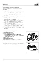
7. Drive the machine close enough to the accessory equipment
until the quick-change unit is correctly positioned under the
holding hook (1) of the accessory equipment
8. Operate the lift / lower control lever so that the accessory
equipment hooks in and raises slightly from the ground.
9. Activate the holding brake.
10. Turn off the engine and remove the ignition key.
11. Move all operating levers of the working hydraulics to both
sides repeatedly.
The hydraulic system is decompressed.
000041
1
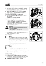
12. Lock the quick-change unit:
– Pull the locking shaft (1) on the handle outwards.
– Turn the locking shaft so that the locking pin (3) is no
longer pushing against the locking bar (4).
The locking shaft locks into place in the outer support (2) and
secures the accessory equipment.
000042
1
3
4
2
WARNING!
Unsecured accessory equipment can fall down and
cause serious accidents.
•
Ensure that the holder is secured.
13. Connect the hydraulic hoses from the accessory equipment to
the quick-release couplings of the machine according to the
identification marking "L2" and "L3".
Drive circuit "L2"
000044
L2 I
L3 I
L3 II+
L2 II
1
NOTE!
Use the overflow oil line if the hydraulic oil is to only
flow in one direction through the accessory equipment
(e.g. with a free turning road sweeper, rotary mulching
mower, auger feeder). In this way, the hydraulic oil
flows back directly into the machine and does not heat
up.
The overflow oil line connection (1) replaces the
connection "L2 I".
Drive circuit "L3"
NOTE!
When using a road sweeper, please check to make
sure that the connection "L3 II+" is used as flow line.
14. If present, shift the support legs from the accessory equipment
upwards and secure these.
15. Start the engine.
16. Release the holding brake.
17. Before starting work, check the functioning of all hydraulic
drive circuits and the functions of the accessory equipment as
described in the accessory equipment operating manual.
The accessory equipment is ready for operation.


