


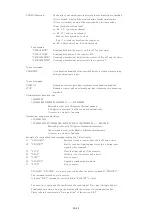

STOP:
When upward edge signal is "ON" ("H"), counting action stopped. (INPUT)
Normally (not connected) STOP signal is "L".
GATE:
When GATE signal goes "L", count action stopped during this level. (INPUT)
When it goes "H", count action starts again.
Normally (not connected) GATE signal is "H".
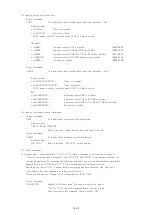
⑦
TTL (3.3V) output connector while counter is operating.
You can synchronous operation by the highest counter if you connect GATE connector of
other modules.
With inner DIP switches, you can invert logic level on START, STOP, GATE, and RUN
signals. Default setting is "ON" ("H"). If you change corresponding DSW2 switches
on printed-circuit board ON to OFF, they changes "OFF" ("L").
⑧
This one is ETHERNET(LAN)connection port. It's adapted to 10BASE-T,100BASE-T
communication.
⑨
This one is USB port.
⑩
Select Encorder Counter type for ⑫ connector
L.D: Line driver
O.C: Open collector
⑪
Selsect Termination(120Ω)
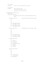
⑫
Input Signals from Encorder counter
Pannel side connector
SRCN2A16-10S(JAE)
Cable side connector
SRCN6A16-10P(JAE)
Line driver input (in case of pin4-5. pin6-7,pin8-9 are also same)
Select termination
by ⑪ switch
⑬
Fuse holder 3A(200V) mini fuse available.
⑭
AC90V to 240V power supply cable.
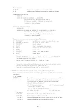
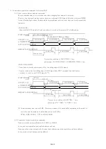
1-3.Block diagram(CT08-ER2)
2
(N.C)
Phase Z
F.G
GND
(N.C)
Phase A
(N.C)
8
9
10
GND
(N.C)
Phase A
Phase A ̄
Phase B
Phase B ̄
Phase Z
Phase Z ̄
F.G
3
4
5
6
7
1
Line driver
+5V
Open Collector
+5V
Phase B
(N.C)
120Ω
pin4
pin5
11/43


