


I)
J)
K)
L)
M)
N)
O)
P)
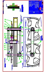
oil, place installation sleeve over shaft and push shaft seal onto shaft (lip facing down) until it contacts thrust
washer. Remove installation sleeve and lightly coat backup seal (6) with clean oil. Install backup seal (6) with lip
facing down followed by metal backup shim (5) (See Figure 1 for correct seal position). Install seal carrier (14)
onto shaft with large end facing down. Using a sleeve and press, gently press seal carrier (14) down to compress
seal assembly (5-7) into seal carrier (14).
Place housing (28) on clean, flat surface with pilot facing up. Place spacer under housing (28) to prevent shaft
(29) from dropping to work surface. Spacer should allow shaft to be about 1/2" below rear surface of housing.
Place shaft/shaft seal assembly into housing (28) with output end facing up. Install high pressure seal (4) into
groove in inner bore of housing (28). Install metal backup shim (3) against high pressure seal (4) by squeezing
the shim (3) between thumb and forefinger to bow shim. While maintaining bow in shim, start the shim into the
groove and use a small screwdriver to push the shim into groove. Install wire ring (2) into groove making sure that
the ends are butted.
While holding shaft into housing, secure housing/shaft assembly in vise with shaft end down. Install drive link (30)
into shaft and gently tap drive link (30) down to seat seal carrier (14) against wire ring (2). Place thrust bearing
(24) over drive link and onto rear surface of shaft (29). If shaft (29) is seated properly against wire ring (2), the
thrust bearing (24) should be flush with rear surface of housing (28).
Install housing seal (8) into groove in housing (28). Place divider plate (31) onto housing (28) aligning bolt holes.
Place body seals (9) in grooves in both sides of rotor (32). Place rotor (32) onto divider plate (31) with side of rotor
with chamfer in splines facing divider plate (31). Place manifold (33) onto rotor (32) with seal groove side up.
Install manifold seal (10).
Install the commutator seal (11) into the commutator (34) with the metal side facing up. Use finger pressure to
press the seal down flush with the surface of the commutator. Place the commutator container onto the manifold
(33) and then place the commutator onto the protruding end of the drive link (30) making sure that the seal side
faces up.
Install the remaining body seal (9) in the groove in the face of the endcover (37). Install piston spring (36) into
endcover (37), then the white backup seal (13) followed by the O-ring seal (12). Lining up the alignment pin with
the hole in the endcover, press piston (35) into the endcover (37). While holding the piston (35) in the endcover
(37), lower the endcover assembly onto the motor. Check to make sure that the endcover ports are in their original
position.
Install the seven assembly bolts (39) and pre-torque to 10 ft. lbs. Using bolt torque sequence shown in Figure 2,
final torque all bolts to 50 ft. lbs.
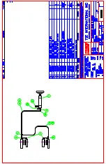
DIRECT DRIVE OPTION (USES ITEMS 40-44)
Place spacer (44) over shaft (29). Place driver (43) over shaft (29) while rotating wheel flange (19) slightly to allow
splines to mate. Place paper gasket (42) onto wheel flange (19). Reapply grease between driver (43) and end
cap (41) (Only if end cap (41) does not have grease fitting). Place end cap (41) onto wheel flange (19). Install six
bolts (40) and torque to 50 ft. lbs. Using the bolt torque sequence shown in Figure 3. If end cap (41) has grease
fitting, apply grease.
WARN HUB OPTION (USES ITEMS 45-48)
Place warn hub spline assembly (48) into wheel flange (19) while rotating wheel flange (19) slightly to allow
splines to mate. Install wire ring (47). Align screw holes of warn hub (46) with screw holes in warn hub spline
assembly (48) and gently press together. Install six screws (45) into warn hub (46) and torque to 27-31 in. lbs.
Содержание T50 BWRC
Страница 11: ......
Страница 12: ......
Страница 24: ......
Страница 25: ......
Страница 26: ......
Страница 27: ......
Страница 28: ......
Страница 29: ......
Страница 30: ......
Страница 31: ......
Страница 32: ......
Страница 33: ......
Страница 34: ......
Страница 35: ......
Страница 36: ......
Страница 37: ......
Страница 38: ......
Страница 43: ...www dexteraxle com OPERATION MAINTENANCE SERVICE MANUAL 600 8 000 lb Axles Related Components ...
Страница 125: ...Service Record Date Service Performed Mileage ...
Страница 126: ...Service Record Date Service Performed Mileage ...
Страница 127: ...Service Record Date Service Performed Mileage ...