background image

 TC 2020R Installation 

TR22.1 2020 Installation with SMC_July_03 

14

 
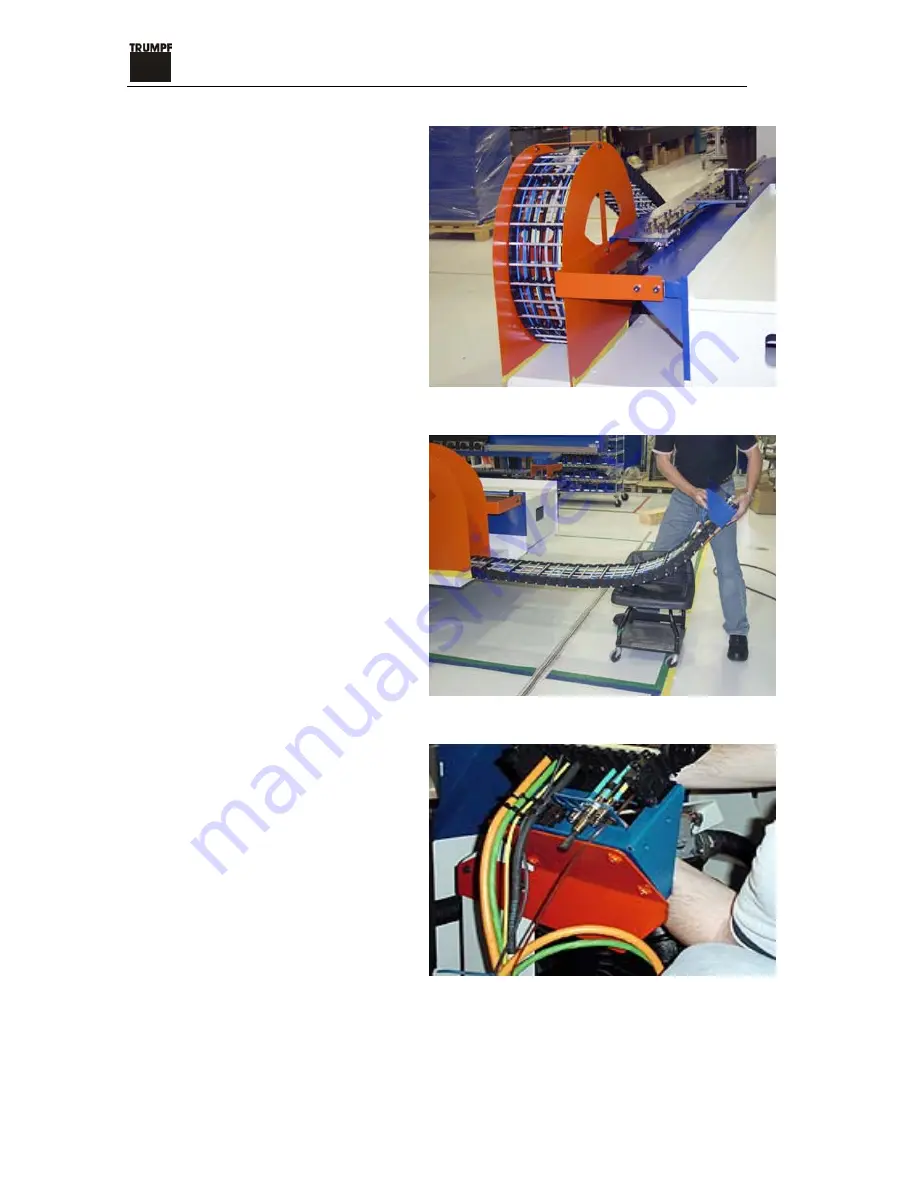
31. Remove shipping bracket for the 

energy chain. 

Figure 32. Energy chain shipping bracket 


32. Pay attention to the energy chain. 

Do not snap the chain. 

Figure 33. Lay the energy chain on a support 


33. Remove the energy chain hold-

down bracket. 

Figure 34. Energy chain hold-down bracket 

Содержание TC 2020R

Страница 1: ...TC 2020R Install with SMC Student Guide For TRUMPF Service Engineers TR22 1 July 2003 ...

Страница 2: ... site 4 Inventory all the parts that came with the machine and inspect the parts for damage If the parts are damaged record the damage take pictures and call TRUMPF Service department 860 678 8584 5 Verify machine options according to the list 6 Inspect the installation area making sure there is adequate room Make sure there are no cracks between the support feet of the machine Check floor for pro...

Страница 3: ...3 8 Determine the center point of the machine Go 3 feet each direction from the center point Swing a 5 feet arc from each of the 3f mark Center 4 f 5 f 5 f 3 f 3 f Figure 1 Mark the center of the machine Figure 2 Measure the distance from 3f mark to the center point ...

Страница 4: ...lation with SMC_July_03 4 9 Make sure the arc intersection is 4f perpendicular from the center point Figure 3 Determine the center of the machine Figure 4 Use plumb bob to determine the center Figure 5 Make sure the plumb bob is in the center ...

Страница 5: ...ds Big pads P3 P4 go to the front of the machine small pads P1 P2 go to the back of the machine Figure 6 Wedge pads come in 2 different sizes 11 Set pads to the correct locations Lay pads down with rubber side facing up and adjusting bolts facing outward Figure 7 Front left wedge pad Figure 8 Back left wedge pad ...

Страница 6: ...tallation TR22 1 2020 Installation with SMC_July_03 6 Figure 9 Back right wedge pad Figure 10 Front right wedge pad 12 Remove shipping wood blocks under the machine Figure 11 Wood block for the back for the machine ...

Страница 7: ...llation with SMC_July_03 7 13 Use crane to lift the machine and carefully position it on wedge pads Figure 12 Front left wedge pad Figure 13 Back right wedge pad 14 Front pads should be flush with machine feet Figure 14 Front right wedge pad ...

Страница 8: ...al Figure 15 Adjusting leveling pads 16 Using strap not chains remove the carriage from the mounting brackets Set the X axis carriage in place and clean and dress all the mating surfaces Figure 16 Remove the carriage from the mounting brackets 17 Using a forklift or overhead crane position the carriage Caution Do not attempt to move by hand Figure 17 Forklift ...

Страница 9: ...between the lifting strap and X rail 19 Find at least two people to assist in guiding the carriage to its correct location Figure 19 Guiding the carriage to its correct location 20 Remove the bolts and prepare the mounting surface for installation Note Observe the location of the bolts upon removal since not all of the bolts are the same length Figure 20 Bolts on the mounting surface ...

Страница 10: ...3 10 Note Care must be taken when mounting the carriage to prevent damage to the precision mounting surfaces Figure 21 X axis rail carriage 21 Make sure all the shims and spacers are underneath the carriage 22 Install stiffeners and outriggers Figure 22 Outriggers ...

Страница 11: ...frame are used to support the outrigger upon installation 23 Install the X axis carriage stiffing bars to both sides of the Y axis Note Alignment pins are installed at the front and back of the stiffing bar Figure 24 X axis carriage stiffing bars 24 Tighten bolts on the support strut Figure 25 Support struts ...

Страница 12: ...th SMC_July_03 12 25 Install the stiffing bar to the underside of the X carriage Figure 26 Underside of the X carriage 26 Install the left and right tables Figure 27 Install right and left tables 27 Install two bolts in each table Figure 28 Two bolts ...

Страница 13: ... 29 Roughly level the machine using a precision machinist s level positioned in the die base Adjust the pads so that the height of machine is 1020 mm Make sure the weight is distributed equally on all pads Figure 30 Precision machinist s level 30 Remove all the shipping brackets 7 in total Clean rails thoroughly make sure all mating surface is chip free Figure 31 Orange shipping brackets ...

Страница 14: ...emove shipping bracket for the energy chain Figure 32 Energy chain shipping bracket 32 Pay attention to the energy chain Do not snap the chain Figure 33 Lay the energy chain on a support 33 Remove the energy chain hold down bracket Figure 34 Energy chain hold down bracket ...

Страница 15: ... bracket Figure 35 Machine hold down shipping bracket 35 For shipping purposes measure the height of the shipping brackets It should read 32 mm Figure 36 Measuring the height of the bracket 36 Measure the Y axis guide rail in front of the bearing block It should read 452 mm Figure 37 Measure the Y guide rail ...

Страница 16: ...ove the shipping brackets for the X axis rail carriage Figure 38 Shipping brackets 38 Remove the two rail covers from the X axis rail carriage Figure 39 X axis carriage cover 39 Remove the bolts on the X axis rail carriage cover Figure 40 Bolts on X axis rail carriage cover ...

Страница 17: ...rail carriage cover Figure 41 Remove X axis rail carriage cover 41 Connect the energy chain to the carriage Make sure all the hydraulic pneumatic and electrical connections are in place Check for proper labeling Figure 42 Energy chain Figure 43 Connect energy chain to the rail carriage ...

Страница 18: ...2 Connect the two black hydraulic hoses Make sure the hoses stay down in the tough Figure 44 Connect lube lines 43 Make sure all fittings and connections are tight Figure 45 Connect air hoses 44 Make sure not to kink any of the pneumatic lines Figure 46 Pneumatic lines ...

Страница 19: ...ctions 45 Connect the X axis motor cable Make sure plugs are properly aligned Make sure motor cables are tight Figure 48 X axis motor cable 46 After all the connections are made do not put the X axis rail cover on just yet Power up the machine and check to see if the hydraulic lines are leaking Caution ...

Страница 20: ...22 1 2020 Installation with SMC_July_03 20 47 Connect 2 the pneumatic lines for the load pin Figure 49 Pneumatic line for the load pin 48 Connect cables for the proxy switches Figure 50 Load pin for automatic sheet loader SMC ...

Страница 21: ...pty hydraulic tank and remove 3 shipping bolts that connect the tank to the machine Position the tank of an inch away from the machine Check hoses level the hydraulic tank and lock down the leveling feet Figure 51 Gap between the tank and the machine 50 Remove cable trough cover Figure 52 Cable trough cover ...

Страница 22: ...ly_03 22 51 Remove all side covers to prepare for cable installation Remove cables out of the cabinet untie them and sort Figure 53 Remove cables from the side panel 52 Sort black and grey drive cables to the back of the machine Figure 54 Black and grey cables ...

Страница 23: ...tion with SMC_July_03 23 53 Sort orange power and green encoder cables and move them to the front of the machine Figure 55 Orange and green cables 54 Move the electrical cabinet into a rough position Figure 56 Machine cabinet in rough position ...

Страница 24: ...rical cabinet to its final position Figure 57 Final position for the electrical cabinet 57 Move the electrical cabinet into its final position 6 inches away from the machine Make sure cabinet is not making contact with the machine Make sure the cabinet door is flush with the side panel of the machine Figure 58 Electrical cabinet Caution ...

Страница 25: ...move the access panel on the bottom of the electrical cabinet Figure 59 Access panel 59 Make all necessary connections Connect the drive cables first Figure 60 Connect all the power cables 60 Hold the power cables in place with the grounding clips Figure 61 Grounding clips ...

Страница 26: ... Installation with SMC_July_03 26 61 Bring the green encoder cables in through the bottom panel Figure 62 Green encoder cables 62 Route the green cables through the wire tough inside the cabinet Figure 63 Wire tough inside the cabinet ...

Страница 27: ...0 Installation with SMC_July_03 27 63 Pay attention to the pins on the plugs of the green cables The pins could get bent Figure 64 Fasten encoder cables with a screw driver Figure 65 5 encoder cables Figure 66 Power and encoder cables ...

Страница 28: ...ble channel 64 Remove the foot paddle switch cable re route it to the electrical cabinet s side 65 Find the position for the control panel from the floor plan in the pre installation manual Make chalk lines 66 Install the anchor lags for the control console Figure 68 Anchor lags for control console ...

Страница 29: ... with SMC_July_03 29 67 Carefully place the console over the lag bolts and tighten to the floor Figure 69 Control console 68 Insert ProfiBus cable in the wire trough Figure 70 ProfiBus cable 69 Put the wire trough wire back on Figure 71 Wire trough ...

Страница 30: ...03 30 70 Make sure the switch on the ProfiBus plug connecting to the CRT console is in the ON position Figure 72 Switch on the ProfiBus 71 Loosen the screw on the ProfiBus plug Figure 73 ProfiBus plug 72 Plug ProfiBus to the control Figure 74 ProfiBus Connection ...

Страница 31: ...allation with SMC_July_03 31 73 Place cables inside the cable guard 74 Install the wire trough and route the control cabinet cables through the conduit on the J frame to the electrical cabinet Figure 75 J frame Figure 76 Conduit in J Frame ...

Страница 32: ...nsole Route the ProfiBus cable through conduit in the J Frame Figure 77 ProfiBus cable routed through conduit in J Frame 76 Install the foot switch cable the sheet clamp cable and the ASI board Figure 78 Foot switch cable 77 Install the light barrier cable to the electrical cabinet through the conduit in the J frame Figure 79 Light barrier cable ...

Страница 33: ...Install and level the light barrier post to the machine frame Figure 80 Light barrier post 79 Remove C frame cover to access hydraulic oil pump Install the adapter supplied with the machine Figure 81 Adapter 80 Open the return line filter Figure 82 Return line filter cap ...

Страница 34: ... 82 Use an electric drill pump the oil into the hydraulic tank through the 6 micron return line filter canister Fill MOBIL DTE25 to the top of the sight glass Figure 84 Electric drill 83 After filling the hydraulic tank use the filter wrench supplied with the machine to remove the top of the filter canister Replace the filter element supplied with the machine Figure 85 ...

Страница 35: ...SMC_July_03 35 84 Change the return line filter after filling the hydraulic tank Figure 86 Return line filter Figure 87 New Return Line Filter Supplied with the Machine 85 Close the drain valve on the accumulator Figure 88 Drain valve on the accumulator ...

Страница 36: ...6 86 Mount the light barrier post to the electrical cabinet Figure 89 Light barrier post 87 Connect the ASI bus Figure 90 ASI bus Figure 91 Foot pedal cable for the sheet clamp open close to be connected to the ASI board located at the rear right side of the machine ...

Страница 37: ...July_03 37 88 Connect the linear amplifier cable M 30 A1 X52 Figure 92 Linear amplifier cable 89 Turn on the power on the wall Check transformer phasing Check phase to phase and phase to ground Figure 93 Transformer 90 Check tabs on the transformer Figure 94 ...

Страница 38: ...92 Power up the electrical cabinet Check LEDs on drives they should show a circle and five 4s Make sure the vacuum is blowing not sucking 93 Connects type 3 communication cable to the DCIO board Note M 30 A1 X35 is not connected Check to see if you get a straight horizontal line on the ANCI board and 1 green light on the DCIO board Figure 96 Type 3 communication cable ...

Страница 39: ...on the MurrLinker you should see 1 dot and 4 green lights On the PLC board on the I O module 1 red dot 95 If control displays error messages about light barrier make a daisy jumper at location M 20 X1 Figure 97 Daisy jumper 96 Locate M 20 X1 from the Schematics Figure 98 M 20 X1 in the Schematics ...

Страница 40: ... pins 1 3 and 4 on the light barrier circuit breaker 98 Start the machine and reference 99 Install the tapered alignment pins prior to mounting the installation bolts Figure 99 Alignment pin 100 Using a threaded bolt and a light hammer tap the alignment pin into place Figure 100 Alignment pins ...

Страница 41: ...Apply 242 thread lock lock tight to all threaded hardware Figure 101 242 thread lock 102 Tighten the 8 mm mounting bolts found within the carriage Figure 102 8 mm mounting bolts 103 Connect the ground wires to the ground clip in the control cabinet Figure 103 Ground wires ...

Страница 42: ...mote control pedestal in position according to the pre installation manual Figure 104 Remote pedestal cable 105 Route the remote pedestal cable through the cable channel on the electrical cabinet side of the machine Figure 105 Remote pedestal cables Figure 106 Remote pedestal cable ...

Страница 43: ...igure 107 Connect cables to the remote pedestal 106 Install the cable guard for the remote pedestal control Figure 108 Cable guard for the remote control pedestal 107 Install anchors in floor for each light barrier mirror post Figure 109 Anchors for light barrier posts ...

Страница 44: ...r light barrier posts 108 Place leaving plate on floor prior to installing the light barrier post Figure 111 Leaving plate for light barrier posts 109 Install the light barrier post by lining up the grooves in the light barrier post to the marks on the leaving plate Figure 112 Light barrier post ...

Страница 45: ...rier post while observing the bubble leave on the top of each unit Figure 113 Leaving plate set screws 111 Line up the indicating marks on the alignment fixture and the light barrier post Figure 114 The indicating marks on the alignment fixture 112 Alignment Fixture Laser Unit and Mounted Bracket Figure 115 Alignment fixture ...

Страница 46: ...C_July_03 46 113 Adjust the reflector mirrors Figure 116 Reflector mirrors on the light barrier 114 Remove cover plate Figure 117 Cover plate on the light barrier 115 Use the adjusting bolts to adjust the reflector mirrors Figure 118 Mirror adjusting bolts ...

Страница 47: ...uly_03 47 116 Adjust the mirror adjusting bolts to direct the light beam from the sending unit to the receiving unit Figure 119 Mirror adjusting bolts 117 Turn OFF the power and check all the electrical connections for tightness 118 Check for hydraulic leaks ...

Страница 48: ...TC 2020R Installation TR22 1 2020 Installation with SMC_July_03 48 Figure 120 Machine accessory tool kit ...

Страница 49: ...2 adapters punch chucks etc 6 Verify that customer has a quick set multi set or the tool alignment fixture that comes with the TC2020 to properly setup tooling 7 Discuss part programming software with customer and problems associated with 3rd party programming systems Particularly incorrect accel decel and sheet type data that can be damaging to the machine 8 Have machine set into place and ensure...

Страница 50: ...ts from hydraulic tank and move 20mm away from J frame 23 Check hydraulic tank filter and assist customer in filling hydraulic tank Mobil DTE25 24 Set operator console into place 25 Route cables for operator consoles through machine frame and connects to proper locations 26 Route the ProfiBus cable purple through the machine frame to the operator console and attach 27 Connect machine to electrical...

Страница 51: ...ormer taps M4 T1 to achieve 220 230vac Voltage ______________ VAC 36 Check voltage at the 24VDC power supply for the machine and verify that it is between 25 74 and 26 26 VDC M4 PWS1 Voltage DC ____________ VDC 37 Check to ensure that the ASI power supply is 15VDC on the ASI connection and 15VDC on the ASI connection The ASI units will operate intermittently if one side is shorted 38 Have customer...

Страница 52: ...to tracks covers cabinet doors etc ensure that everything is grounded properly 49 Clean Cosmoline from all surfaces do not use water based or harsh solvents 50 Inspect V ring seal door on vacuum system and ensure they are clean 51 Ensure screens on vacuum system are clean and inspect all hoses 52 Ensure silencers on vacuum system are clean 53 Check to ensure vacuum system exhaust is facing AWAY fr...

Страница 53: ...cap tool change height 52 2mm 69 Ensure table support rollers make contact with tables properly and that tables are 5 1 mm above a new die 70 Verify that the machine s reference offsets match its paperwork and correct the paperwork if necessary 71 Check the feed hold key switch for proper operation 72 Check all buttons on remote pedestal for proper operation 73 Check door interlock switch on elect...

Страница 54: ...worktables are not rubbing the fixed brush table in center of J frame 86 Check 0 point of C axis 87 Check for worn or damaged hydraulic hoses 88 Ensure clamps aren t damaged and are clean 89 Inspect tool holder and rail area for damage and cleanliness 90 Check punch height sensors for proper alignment and operation 91 Check stripper sensor for proper alignment and operation 92 Run a part program a...

Страница 55: ...2020 Installation with SMC_July_03 55 96 Show customer where to make network connections 97 Discuss the importance of the die base tapered alignment pins that come in the tool kit for the machine and why they should keep them handy ...

Страница 56: ...customer how to load program from the A drive and also there net work drive 7 Show customer how to stop the machine quickly if they see something is wrong 8 Show customer receiving ring and discuss its importance 9 Show customer how to properly set up tooling and how to read the tool table 10 Show customer how to shutdown machine properly 11 Show customer how to delete programs from memory 12 Show...

Страница 57: ...es for machine and move tables manually 21 Show customer e stop limits for x y axis and all other devices that may keep the machine from operating 22 Discuss the importance of operating the machine safely and properly 23 Show customer the stripper sensor and reflector Discuss why it should be kept clean 24 Go over all maintenance procedures covered in chapter 6 of the operator s manual 25 Show cus...

Страница 58: ...ation TR22 1 2020 Installation with SMC_July_03 58 29 Go over the machine fault and error list that comes with the machine 30 Ensure the operator feels good in his ability to operate the machine before leaving customer ...

Страница 59: ...5 836 M4 2 858 3 1199 3 5 1441 M5 4 1397 6 1969 7 2354 6 5 2095 8 5 2779 11 3699 M6 7 1980 10 2772 12 3322 11 3168 15 4158 19 5276 M8 18 3630 25 5014 29 6138 4 4936 31 6416 41 8533 M10 35 5764 49 8118 59 9746 41 6822 54 9591 70 11507 M12 62 8426 86 11880 104 14190 69 9503 86 11880 108 14679 M14 97 11550 137 16280 165 19470 M16 151 16060 212 22440 256 27060 155 16442 216 22820 259 27827 M18 209 193...

Страница 60: ...lack and grey cables 2 Jog X axis to the center of the machine Measure from clamp 9 to the die base The distance should be within 150 mm to 300 mm Repeat the procedure for clamp 20 Figure 122 Measure from the center of the clamp to the die base 3 Drop 2 plumb bobs from the center of the clamp edges to the floor Figure 123 Drop plumb bob from the edge of the clamps ...

Страница 61: ...ion TR22 1 2020 Installation with SMC_July_03 61 4 Make a mark on the floor Figure 124 Make a mark on the floor Figure 125 Make a mark on the floor 5 Measure from the chalk line 150 mm Figure 126 Make a mark on the floor ...

Страница 62: ...SMC_July_03 62 6 Snap another chalk line This will be the zero point for the X axis Figure 127 Snap another chalk line 15 mm from the first one 7 Jog Y axis out of the machine in the direction Shut off hydraulics Figure 128 Y axis rail out of the machine ...

Страница 63: ...020 Installation with SMC_July_03 63 8 Drop a plumb bob from the front edge of the Y rail Figure 129 Plumb bob at front of Y rail edge 9 Drop another plumb bob from the back of the Y rail Figure 130 Plumb bob at back of Y rail edge ...

Страница 64: ..._July_03 64 10 Snap a line to establish the 565 mm line Figure 131 Chalk line at 565 mm 11 Measure 165 mm from the 565 mm line Figure 132 15 mm from 565 mm line 12 Snap another chalk line parallel the 565 mm line Figure 133 Lines at 565 mm and 400 mm 165mm ...

Страница 65: ...July_03 65 All chalk lines for the templates are now finished Figure 134 Chalk lines for laying the templates 13 Unpack the SMC 14 Lay down templates starting with the top right corner Spray paint drill holes let dry for 15 minutes Figure 135 Template 1 B C ...

Страница 66: ...TC 2020R Installation TR22 1 2020 Installation with SMC_July_03 66 15 Lay down template 2 Figure 136 Template B A G 16 Lay down template 3 Figure 137 Template C D ...

Страница 67: ...TC 2020R Installation TR22 1 2020 Installation with SMC_July_03 67 17 Lay down template 4 Figure 138 Template D A E ...

Страница 68: ...SMC precision rails toward the machine non precision rails with notch to back of the C frame Figure 139 Non precision rail for the SMC 19 Build a target pole with measuring tape Figure 140 Transit pole with measuring tape 20 Set up the Transit starting with the tripod Figure 141 Transit tripod ...

Страница 69: ...tion with SMC_July_03 69 21 Secure the tripod legs Figure 142 Tripod 22 Set up the optical level Figure 143 Optical level 23 Zero the optical level then align and fine tune the optical level in all directions Figure 144 Align the optical level ...

Страница 70: ...on with SMC_July_03 70 24 Read the height at the front end of the center rail Record the value Figure 145 Center rail front 25 Read the height at the back end of the center rail Record the value Figure 146 Center rail back Figure 147 Read heights ...

Страница 71: ... the heights of the left rail and record the values Figure 148 Left rail non precision rail 27 Read the heights of the right rail and record the values Figure 149 Right rail precision rail 28 Find the highest rail point and adjust other leveling screws to match it Figure 150 ...

Страница 72: ...ure 151 Leveling screw 29 Tighten bolts down Do the bolts on the ends of the rails first then lock down with floor bolts Figure 152 Bolts on non precision rail 30 Use a level to keep rail level from side to side Figure 153 Adjust leveling screws to match the highest point ...

Страница 73: ... with SMC_July_03 73 Figure 154 Tighten bolts on the precision rail 31 Install cable guards for the proxy switch Figure 155 Cable guards 32 Install sheet sensor posts for the pallets short post goes inside long one outside Figure 156 Sheet sensors ...

Страница 74: ...nsor posts to the drill holes on the floor Figure 157 Sensor post aligned with drill holes 34 Connect sheet sensor cable to the electrical cabinet Figure 158 Sheet sensor cable 35 Use the forklift to bring in bottom pallet and carefully set the bottom pallet on rails Figure 159 Bottom pallet ...

Страница 75: ... 75 36 Remove the panel on the back of the bottom pallet Figure 160 Panel on the bottom pallet 37 Turn the cam inside the panel to either 3 or 9 o clock position 38 Install 2 black plates on each side of the SMC 39 Mount the SMC into position Figure 161 Install SMC ...

Страница 76: ...n with SMC_July_03 76 40 Carefully align the back corner holes on the SMC foot to the drill holes on the floor Figure 162 Bolts Figure 163 Holes aligned with the drill hole 41 Lay a full sheet on the table and open the clamps Figure 164 Load sheet ...

Страница 77: ...s Figure 165 Slide sheet against the clamps 43 Check to see if the sheet slides in without rubbing the bottom of the clamp jaw Figure 166 Clamps higher than the sheet 44 Move Y axis to the mid point of the machine Adjust the roller underneath the tables to raise the height of the table Figure 167 Rubber roller underneath the table ...

Страница 78: ...roller wheel bolts Figure 168 Jacking nuts on roller 46 Move Y axis in the direction out of the machine Install brush extension table Figure 169 Adjoining side between steel table and the brush table 47 Remove all the bolts and replace them with 10 bolts and 10 washers Figure 170 Remove bolts on the steel table side ...

Страница 79: ...ttention to the boltholes Figure 171 49 Install the stiffening bracket underneath the brush table Figure 172 Stiffening bracket under the brush table 50 Have two people holding the table while the third person installing the bracket underneath Figure 173 Brush extension table ...

Страница 80: ...smoothly onto the brush table Figure 174 Check height of the brush table 52 Remove all covers and shipping brackets on the SMC Remove the 2 panels on the back of the SMC to access air regulator and the piston for the gripper table Figure 175 Shipping brackets on SMC 53 Release the crank arm on the piston for the gripper table Figure 176 Crank arm ...

Страница 81: ... 2 air hoses from the piston and from under the gripper table Figure 177 Air hoses under the gripper table 55 Push the gripper table toward the machine Figure 178 Gripper table 56 Slide sheet into the grippers Check gripper height against the machine table Figure 179 Gripper clamps ...

Страница 82: ...he bottom of the sheet Figure 180 Gripper clamps 58 Adjust the base screws on the SMC to bring the loader height to the machine height Level the SMC with one bolt in the front and one bolt in the back Figure 181 Front screw 59 Lock down the rest of the screws until they just touch the floor Figure 182 Base screws on the SMC ...

Страница 83: ...eck gripper height again Figure 183 Gripper jaws 61 Adjust grippers so that they are in the center of the table slots Figure 184 Table slots 62 Loosen 4 screws one turn above each gripper to center the gripper Tighten bolts when done Figure 185 Adjusting screws for grippers ...

Страница 84: ...back on Figure 186 Air lines and crank arm for the piston 64 Start up the machine Jog Y axis in the direction out of the machine Reset the clamp height In the Switch Elements open the workpiece clamps Figure 187 Open workpiece clamps 65 Turn off the hydraulics Mount 2 rubber bushings to the 2 lower holes on the lower rail buttress Figure 188 Rubber bushings ...

Страница 85: ...for the front table support arms 67 Using either a pry bar or a big wrench jack the table higher than needed due to springback until the workpiece can slide easily onto the lower jaw of the clamps Tighten the bushings Figure 190 Jacking up table with a pry bar 68 Check sensors on the clamps First remove the cover on the clamps by loosening 3 screws Figure 191 Clamp cover ...

Страница 86: ...TC 2020R Installation TR22 1 2020 Installation with SMC_July_03 86 69 Remove the bottom screws on the cover Figure 192 Lower screw on the clamp cover 70 Remove the clamp cover Figure 193 Clamp cover ...

Страница 87: ...2020R Installation TR22 1 2020 Installation with SMC_July_03 87 Figure 194 Location of clamp sensor 71 Use the clamp sensor testing fixture to check sensor settings Figure 195 Clamp sensor testing fixture ...

Страница 88: ...gest notch is pushed against the cam it should be AMBER when the shallow notch pressed against the cam it should be green when the smooth edge is pressed against the cam Figure 197 Pressing fixture against cam 74 Use an Allen wrench to adjust the sensor settings while the fixture remains pressed against the cam 75 Repeat the same procedure for the other clamp sensor 76 Load a sheet and check to se...

Страница 89: ...he end pieces to the center bracket first and mount the brackets as a unit Figure 199 Back edge brackets 78 Loosen the mounting screws corresponding to slots on the brackets Figure 200 Mounting screws 79 Adjust height of the bracket unit until it is just below the workpiece Tighten screws Figure 201 Check back edge brackets ...

Страница 90: ...81 Connect cable for the proxy switch Figure 203 Proxy switch cable 82 Turn on the machine Align pallet sensor posts with the reflector sensors on each side of the back frame until the lights come on solid The lights on the left side should be YELLOW and the lights on the right side should be GREEN Figure 204 Pallet sensor posts ...

Страница 91: ... 91 Figure 205 Reflector on the SMC frame 83 Run air hose through the base of the C frame up through the SMC column across crossbeam and into the air nipple Tighten hose clamp Figure 206 Air hose 84 Route all cables to the back of the cabinet Figure 207 SMC cables ...

Страница 92: ...frame through top fitting to the lube reservoir Do not kink the blue hose Figure 208 Back frame 86 Route all cables through the hole on the machine to the electrical cabinet Figure 209 Gap between machine and the SMC 87 Installing the I O cables through the conduit and J Frame Figure 210 I O cables ...

Страница 93: ...l connections make sure the connections are tight and secure Figure 212 Electrical and ground connections 89 Route 3 yellow proxy switch cables between the machine and the SMC to the sensor posts and the pallet proxy switch Figure 213 Proxy switch cables 90 Push the air valves in and turn off the suction cups ...

Страница 94: ...tion pallet and floor channel Figure 214 Floor channel 92 The proxy switch inside the bottom pallet should be RED Figure 215 Proxy switch inside the bottom pallet 93 Tape a nickel to the proxy switch to make the connection the light should be RED Figure 216 Pallet proxy switch ...

Страница 95: ...password min 530 Go through all selections n the drop down menu In each selection page down to check for any red highlights Acknowledge all changes by press Current value checked soft key 99 Go to focus menu 1 5 4 highlight machine type in this case TC2020 SMC press Available soft key and then Applications soft key 100 Highlight LS sensor pin time change from 3 000 to 10 000 1ms to set SMC timing ...

Страница 96: ...stop 105 On the control press Set up key press Selection soft key from the drop down menu select SMC keys 2 press ENTER Choose 1 Upper position The suction frame goes up Immediately engage E stop when it reaches the limit 106 Install 4 suction arms in sequence from inside out Figure 219 Suction arms Figure 220 Suction arm in sequence ...

Страница 97: ...ugh the square hole on top of the suction arm Figure 221 Air hose for suction arm 108 Coil the air hose and hold the loop up with 2 clamps underneath the suction arm Figure 222 Loop air hose underneath suction arm 109 Connect the air hose to the suction cup Figure 223 Air hose connections ...

Страница 98: ... reached Figure 224 Grippers 111 Clear tilt sensor Press Set up key Press Selection soft key From the drop down menu select SMC keys 3 Press ENTER Select 1 Load service mode Make sure E stop is ON Press Reset key clear light barrier Drive up the frame until it deadheads Select 1 Load service mode to turn off service mode Press Reset key Start the hydraulics and reference the machine Figure 225 Til...

Страница 99: ...ct SMC keys 1 Press ENTER Select 2 Gripper carriage forward to allow access for forklift Remove nickel from the proxy switch Figure 226 Pallet for unprocessed sheets 113 Load sheet pallet and unprocessed sheets Figure 227 Loading unprocessed sheets to pallet 114 Install parts bin to the side of the machine Start with the stop bracket first Figure 228 Bolts for stop bracket ...

Страница 100: ...machine Test grippers 116 Load software parameters for the SMC Go to focus menu 1 5 1 Press Applications soft key Press ENTER 502000103 index 0 is the standard load pin 502000103 index 1 is the manual load pin 502000103 index 7 is the offset for automatic load pin Positions 14 to 16 are positioning parameters for sheet loading ...

Страница 101: ...r confirming that all the correct addresses are flashing on the screen Press OK Highlight Set up and press OK Highlight Store ACT CNF and press OK Highlight Store and press OK Press Esc button once 3 Highlight Operation mode and press OK Highlight Change and press OK Plug the ProfiBus cable back in Press Esc button 3 times 4 You have to assign a correct ProfiBus address to the Gateway to reconfigu...

Отзывы: