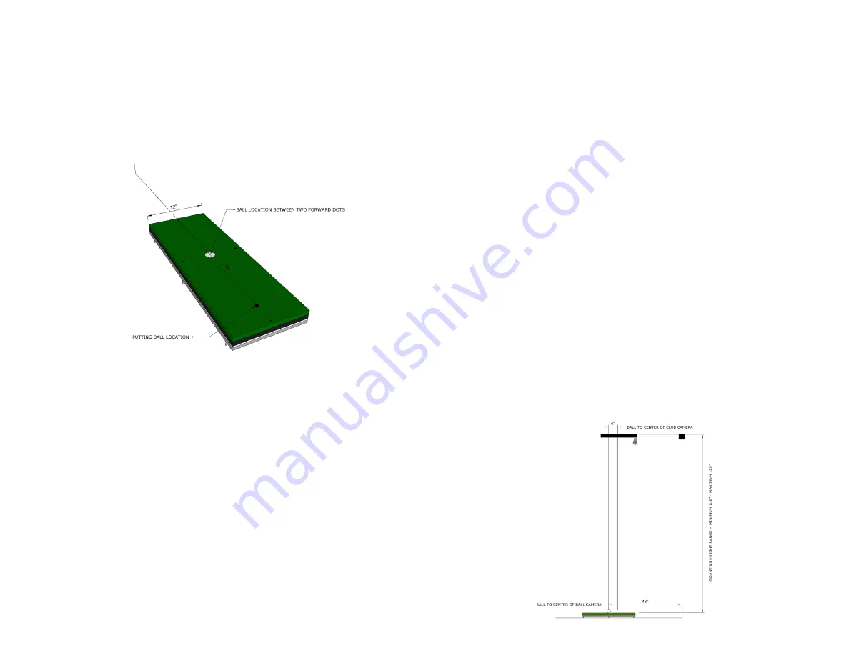
TruGolf TruFlight 2 Скачать руководство пользователя страница 3

2

3

BALL 

PLACEMENT

IMPORTANT! 

WHEN USING THE TRUFLIGHT 2 CAMERA SYSTEM, 

THE BALL IS PLACED IN THE TEE POSITION WHEN HITTING A FULL 

SHOT; WHEN PUTTING, THE BALL MUST BE PLACED BEHIND THE 

TEE POSITION AS SHOWN. IF BALL IS NOT PLACED IN THE CORRECT 

POSITION, SHOTS WILL FAIL TO REGISTER CORRECTLY.

INSTALLATION

Before installing, you must have:


A computer with two open USB ports on the motherboard


»

Intel i7 4 Core Processor


»

16 GB RAM 


»

1-USB 2.0 and 1-USB 3.0


Turf floor covering: Required: 

PL307 Forrest Green Turf 


»

If other, please contact your sales rep at TruGolf


Ladder


Measuring Tape


A drill w/screw bits


Precision Phillips screwdriver


A plumb bob and laser level (for precise alignment)


Masking tape


Level


Two golf balls


Golf Clubs (Wood, Iron, Wedge, and Putter)

1| 

Download and install E6 Connect and TruFlight 2 Installation file 

on your computer. 

E6 CONNECT:


https://e6golf.com/update/e6-connect/ 

Run and ensure that TruFlight 2 is the selected Tracking System.

TRUFLIGHT 2 UTILITIES:


https://trugolf.com/support/ 

This installs all the drivers necessary for TruFlight 2. Continue through 

every window of the installer and accept all default decisions. 

2| 

Position Hitting Mat

• Hitting mat is 

35” x 12” 

or 

89cm x 30.5cm

• Hitting Mat should be located in a position where a golfer would not 

hit the walls while swinging. 

• Commercially recommended at least 

7’6”

 or 

2.3m

 off left/right walls

• 

The Hitting Mat can be set off center in a simulator but, depending on 

space, may eliminate some golfers from being able to swing without 

hitting the wall behind them.

• For safety reasons position the mat at least 

9’ 

away and 

perpendicular to the hitting screen.

3| 

Position the Club Camera housing:

• To identify the center point where the Club Camera enclosure should 

be mounted, place a piece of tape on the ground on the centerline of 

the simulator 

6” 

or 

15cm

 toward the screen from the ball position. 

• Use Plumb Bob or laser level and make a mark for exact placement 

on the ceiling. 

• Install the mount for the Club Camera housing centered on this mark. 
• Must be placed 

108”-120” 

or 

275-305cm

 above the floor and be level 

on all axes.

SIDE VIEW

SCREEN

SCREEN

Содержание TruFlight 2

Страница 1: ...TRUFLIGHT2 SBC MANUAL...

Страница 2: ...olex Cable 2m length 7 33 USB 2 0 Cables 10m length 8 3 Computer Power Cable 9 TruFlight 2 Calibration Grid 10 Reflective Club Stickers 11 Replacement Fuses 12 Mount 13 Mounting Screws TABLE OF CONTEN...

Страница 3: ...GHT 2 UTILITIES https trugolf com support This installs all the drivers necessary for TruFlight 2 Continue through every window of the installer and accept all default decisions 2 Position Hitting Mat...

Страница 4: ...he wall 2 The USB 2 0 cable and the USB 3 0 Fiber optic cable should be run from the computer to the back side of the Ball Camera Enclosure location where the cables are sticking out Handle the USB 3...

Страница 5: ...piece of masking tape Place one golf ball on the masking tape and another golf ball in the exact center of the tee position Select the Camera Alignment Grid checkbox Using your computer keyboard use...

Страница 6: ...ar as it looks at the ball which should still be placed directly under the camera system The goal is to get the number as low as possible then you have the focus set correctly Discard Tape on Ground a...

Страница 7: ...CLUB CAMERA SETTINGS CLUB CAMERA FOCUS Click Show Club Camera Click Start Place a ball in the center of the 3 dots on the hitting mat Move the camera around until the ball is visible in the Live Wind...

Страница 8: ...res Enter number of squares visible into Height Inches field Click Save Changes 15 13 12 10 11 14 TRUFLIGHT 2 CALIBRATION GRID INSTRUCTIONS ALIGN THE HOLES WITH THE MARKINGS ON THE HITTING MAT SCREEN...

Страница 9: ...ld be accurate and need little if any adjustments If adjustments are needed because the launch angles are reported a degree or two high or low then you can change the value stored in the CTFinalLAOffs...

Страница 10: ...h the frames to ensure that the ball and club are marked properly and the ball is showing up correctly in the ball detection window BALL DETECTION TIMING Click Show Club Camera Click Start Hit test sh...

Страница 11: ...peedAdjust number up or down from the default 1 0 value 1 1 would be a 10 increase in ball speed 9 would be a 10 decrease WHAT IF I M GETTING A ZERO DEGREE LAUNCH ANGLE Repeat the step for Ball Camera...

Страница 12: ...1 05000 CTFinalLAConst This is a correction value used if the camera in the ball camera case is not square to the target line down the middle of the hitting mat as described on page 7 ALIGNMENT VISUAL...

Страница 13: ...TRUGOLF COM DRIVINGREALITY GOLFCONNECTED...

Отзывы: