background image

TractionAir

22

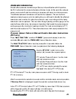
‘Pressure Sensor Fail – Contact Service Agent’

 will not display until the next 

compare failure.

After an alarm, both PT1 and PT2 pressures will be displayed and updated every 
second. This will enable the operator to determine which sensor best matches 
a manual pressure gauge reading of the tyre pressure. a) above is then used to 
select this sensor to control the tyre pressure until the faulty sensor is replaced 
and PT1+PT2 selected.

Pressure Transducer Test

1.  Ensure the ECU is turned on
2.  Go to the Pressure Cell and open the lid.
3.  Using a DC Volt meter measure the Transducer supply voltage between  
 

Terminal 4 (+ve) and Terminal 2. It should be between 8 and 10V. If not  


check that the RED wire is tight in Terminal 4 and that all the pins are    


correctly inserted in the 10 way ECU connector. Then check the wiring loom  


for damage.

4.  If the voltage is OK go to the next step.
5.  Remove the yellow wire from terminal 5 and connect  
 

a DC Amp meter in series with this wire and terminal 2. 

6.  If the reading is not between 4 and 20mA.  
 

(milliamps), you will have to replace the  


pressure transducer.   

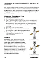
Park up

Taps On (handles in line)

Taps Off (handles at 90 °)

When parking up the vehicle overnight or any 
other extended time period, it is very important 
that 

all wheel end axle bridge ball valves are 

turned off.

 TractionAir can mask small leaks and 

punctures that may be present in a single tyre 
that left overnight, could result in all tyres losing 
pressure and breaking their beads. The ball valves 
located on the two brass TA37004 tees are there 
primarily to allow quick isolation of a wheel group 
in the event of a blown hose etc.  

Leave these taps on overnight.

Содержание TractionAir

Страница 1: ...oom Connection at Pressure Cell 15 Test System 16 TractionAir ECU Operation Functionality 17 Air Leaks 17 Operating Instructions for versions with GPS Speed Up 18 General Operation 19 20 Functions 20...

Страница 2: ...e and functionality for the fleet technician while retaining all of the functionality of the earlier versions Our 5th generation EC9 is a giant leap forward in pneumatic pressure control The EC9 incor...

Страница 3: ...pneumatics system Mounted appropriately on the vehicle chassis the TractionAir G5 Pressure Cell requires only two air line and one electrical loom connection 3 Exhaust 1 To and from Tyres 1 Main Fill...

Страница 4: ...a The short loom is the power supply comprising of two wires refer to ECU wiring diagram on pages 5 The ECU must be protected with either a 2 amp blade fuse located in the fuse board in the vehicle or...

Страница 5: ...st signal Wiring for the Short Lead on the Loom Power and Earth to ECU Note Power to be ignition fed 3 5 1 2 5 6 7 8 9 10 11 12 10 PIN FEMALE PLUG To Rear of TractionAir Controller 2 Core Power 3m to...

Страница 6: ...nt the pressure cell in a position within the chassis to avoid damage a Do not mount the enclosure close to any heat source e g exhaust b Provided in each kitset are four rubber washers approx 15mm lo...

Страница 7: ...outer wheels so that the valve stems are opposite each other 180 degrees apart This may require rotating both inner and outer wheels The easiest way of achieving this is to position the Wheel Bridge s...

Страница 8: ...r feed hose Note Bridge Spacers Bolt will change to suit different vehicles Wheel End Mounting Standard Conventional Rotor TAAG0607 TABV4 PEA7 0404 TAB Check Vehicle Model TADCCC TAD04 TAAB0404 Bolt d...

Страница 9: ...TAABS8 PEA7 0404 TAABHRS TADCACI TABV4 TAABS8I TADCHRHD TAAG0207 TA40335 Note Bridge Spacers Bolt will change to suit different vehicles Heavy Duty High Temperature Hub Reduction Model Wheel End TAHD...

Страница 10: ...TractionAir 10 Wheel End Plumbing Layout Outer Wheel Hose Axle Bridge TRT Rotator External Wheel Hose Inner Wheel Hose Tee Block 3 8 Nylon Tube...

Страница 11: ...TractionAir 11 Plumbing System Auxillary Air Tank Truck Supply Pressure Protection Valve To From Tyres Filter RTN Chassis Rail Chassis Rail Tee Block To Tyres To Tyres Drain Cock Exhaust Vent Inlet...

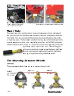
Страница 12: ...cell and then from the pressure cell to the tee between the tyres TA37006 This tee needs to be tted inside the chassis between the centre of the Drive Axles The tube then runs from the Tee piece TA37...

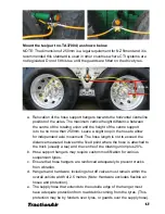
Страница 13: ...o allow for independent axle movement The hose length is not to exceed the distance measured between the xed point where the hose is attached to the truck usually a tee and the centre of the rotating...

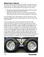
Страница 14: ...ed to seal on the sharp face of the valve stem To t the wheel feed hose attach the 45 degree hose tail to the nipple TAAG0207 tted to the side of the Rotator Run the hose up to the elbow adaptor 45 de...

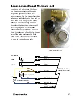
Страница 15: ...iring diagram included at the bottom of these instructions A copy of the wiring diagram is xed to the inside face of the alloy enclosure lid Only hook up the coloured wires required for your kit i e t...

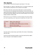
Страница 16: ...with the lowest setting Push the lowest setting maximum traction button NB Pressure can vary 2 PSI Below is a common example of the pressure settings yours may vary depending on your requirement and...

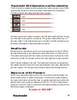
Страница 17: ...a small air leak The system will keep up with the majority of small air leaks however the driver will need to monitor the situation and have the leak attended to when practical Note Pressure changes i...

Страница 18: ...stment is made though the USB connection on the ECU This can be done through your TRT sales consultant or with the software package issued with the EC8 model onwards Operating instructions for version...

Страница 19: ...ed to check the GPS receiver connection to the ECU ensure that there is a clear view of the sky as much as practical and that the vehicle is not parked in a building If this does not rectify the issue...

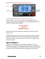
Страница 20: ...he LOADED ON ROAD led will start to flash at a fast rate and a message SPEEDUP ACTIVATED displayed If in five seconds time the speed is still greater than the set kph then the LOADED ON ROAD pressure...

Страница 21: ...Selection Instructions EC9 only Press MAX TRACTION and then POWER press and release to turn the controller ON and enter the PRESSURE Sensor Selection mode The MAX TRACTION button must be pressed for 4...

Страница 22: ...4 and that all the pins are correctly inserted in the 10 way ECU connector Then check the wiring loom for damage 4 If the voltage is OK go to the next step 5 Remove the yellow wire from terminal 5 and...

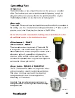
Страница 23: ...will then loosen in the terminals over time Filter Assembly TAAF8 Filter Element TAAFE The pneumatic system component of TractionAir G4 is designed to cope better with the ingress of oil and other con...

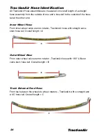
Страница 24: ...at the other end Inner Wheel Hose From inner wheel valve stem to rotator TractionAir hose with straight valve stem hose tail Overall length A A B C Outer Wheel Hose From outer wheel valve stem to rota...

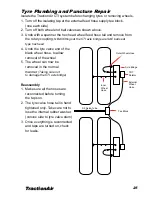
Страница 25: ...x head wheel feed hose tail and remove from the rotary coupling NB All fittings at the CTI axle bridge are SAE ball seat type hex head 4 Undo the tyre valve end of the black wheel hose to allow remova...

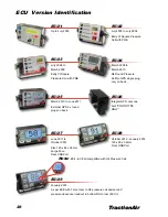
Страница 26: ...er 2012 Size 120 x 64 x 36mm Large Face Rear USB Port Note EC4 EC8 all compatible with G4 Pressure Cell ECU5 March 2010 to June 2011 External GPS 2 x round plugs on back ECU6 Integral GPS only one bui...

Страница 27: ...TractionAir 27...
Страница 28: ...tact TRT Tidd Ross Todd Ltd Head Office Hamilton New Zealand Phone 647849 4839 Website www trt co nz Email tractionair trt co nz Sales Manager Gavin Halley Mobile 64274 522 766 Sales Engineer Craig Bu...

Отзывы: