background image

Auger Control

The auger control is located on the left handle. Squeeze the 

control grip against the handle to engage the augers and start 

snow throwing action. Release to stop.

Drive Control / Auger Clutch Lock

The drive control is located on the right handle. Squeeze the 

control grip against the handle to engage the wheel drive. 

Release the handle to stop. 

The drive control also locks the auger control so that you can 

operate the chute directional control without interrupting 

the snow throwing process. If the auger control is engaged 

simultaneously with the drive control, the operator can release 

the auger control (on the left handle) and the augers will remain 

engaged. Release both controls to stop the augers and wheel 

drive. 
NOTE: Always release the drive control before changing speeds. 

Failure to do so will result in increased wear on your machine’s 

drive system. 

Two-Way Chute Control™

This two-way control lever is meant to control the distance of 

snow discharge from the chute. Tilt the lever forward or rearward 

to adjust the distance snow will be thrown.

Chute Directional Control

The chute directional control can be turned clockwise or 
counterclockwise to change the direction in which snow is 

thrown.

Wheel Steering Controls

The left and right wheel steering controls are located on the 

underside of the handles. Squeeze the right control to turn right; 

squeeze the left control to turn left. 
NOTE:  Operate the snow thrower in open areas until you are 

familiar with these controls.

Chute Clean-Out Tool

WARNING! 

Never use your hands to clear a 

clogged chute assembly. Shut off engine and remain 

behind handles until all moving parts have stopped 

before unclogging.

The chute clean-out tool is conveniently fastened to the rear of 

the auger housing with a mounting clip. Should snow and ice 

become lodged in the chute assembly during operation, proceed 

as follows to safely clean the chute assembly and chute opening:

Release both the Auger Control and the Drive Control.

1. 

Stop the engine. 

2. 

Remove the clean-out tool from the clip which secures it to 

3. 

the rear of the auger housing. 
Use the shovel-shaped end of the clean-out tool to 

4. 

dislodge and scoop any snow and ice which has formed in 

and near the chute assembly.
Refasten the clean-out tool to the mounting clip on the 

5. 

rear of the auger housing, start the snow thrower’s engine.
While standing in the operator’s position (behind the snow 

6. 

thrower), engage the auger control for a few seconds to 

clear any remaining snow and ice from the chute assembly. 

CHUTE DIRECTIONAL CONTROL

DISCHARGE

LEFT

DISCHARGE

RIGHT

CHUTE TILT

DOWN

CHUTE TILT

UP

13

S

ectioN

 4 — c

oNtrolS


aNd

 f

eatureS

Содержание 900 Series

Страница 1: ...p Operation Maintenance Service Troubleshooting Warranty WARNING READ AND FOLLOW ALL SAFETY RULES AND INSTRUCTIONS IN THIS MANUAL BEFORE ATTEMPTING TO OPERATE THIS MACHINE FAILURE TO COMPLY WITH THESE INSTRUCTIONS MAY RESULT IN PERSONAL INJURY www troybilt ca Two Stage Snow Thrower 900 Series 769 06137B 07 19 13 ...

Страница 2: ... yourself with the machine its features and operation Please be aware that this Operator s Manual may cover a range of product specifications for various models Characteristics and features discussed and or illustrated in this manual may not be applicable to all models The manufacturer reserves the right to change product specifications designs and equipment without notice and without incurring ob...

Страница 3: ...he eyes Do not operate without wearing adequate winter outer 2 garments Do not wear jewelry long scarves or other loose clothing which could become entangled in moving parts Wear footwear which will improve footing on slippery surfaces Use a grounded three wire extension cord and receptacle 3 for all machines with electric start engines Adjust auger housing height to clear gravel or crushed rock 4...

Страница 4: ...place and working Never run an engine indoors or in a poorly ventilated area 5 Engine exhaust contains carbon monoxide an odorless and deadly gas Do not operate machine while under the influence of 6 alcohol or drugs Muffler and engine become hot and can cause a burn Do 7 not touch Keep children away Exercise extreme caution when operating on or crossing 8 gravel surfaces Stay alert for hidden haz...

Страница 5: ...minutes to clear snow 9 from machine and prevent freeze up of auger impeller Never store the machine or fuel container inside where 10 there is an open flame spark or pilot light such as a water heater furnace clothes dryer etc Always refer to the operator s manual for proper 11 instructions on off season storage Check fuel line tank cap and fittings frequently for cracks 12 or leaks Replace if ne...

Страница 6: ...et near rotating parts in the auger impeller housing or chute assembly Contact with the rotating parts can amputate hands and feet WARNING THROWN OBJECTS This machine may pick up and throw objects which can cause serious personal injury WARNING GASOLINE IS FLAMMABLE Allow the engine to cool at least two minutes before refueling WARNING CARBON MONOXIDE Never run an engine indoors or in a poorly ven...

Страница 7: ...ome models with electric start are equipped with an extension cord fastened with a cable tie to the rear of the auger housing for shipping purposes Cut the cable tie and remove it before operating the snow thrower Assembling Handle Cut and remove the cable tie holding the chute crank to the lower handle Look at the lower rear of the snow thrower frame to be sure the spring found at the end of each...

Страница 8: ...e adjusted so the spiral on the chute crank fully engages the teeth on the chute assembly Refer to the Adjustment Section Chute Directional Control 1 Remove the hairpin clip from the lower chute crank as shown in A of Fig 3 4 2 Insert the upper chute crank into the fitting on the lower chute crank as seen in B of Fig 3 4 3 Secure with the hairpin clip previously removed Attaching the Chute Assembl...

Страница 9: ... wingnuts securing the drift cutters to the housing Reposition drift cutters so they face forward as shown in Figure 3 9 Secure with hardware previously removed wingnuts should be fastened on the outside of the housing as shown If your unit is not equipped with drift cutters you may contact Customer Support as instructed on page 2 for information regarding price and availability Tire Pressure The ...

Страница 10: ...ut tool is mounted to the rear of the auger housing and is designed to clear a clogged chute See Figure 3 10 Refer to the Operation section for more detailed information regarding the chute clean out tool NOTE This item is fastened with a cable tie to the rear of the auger housing at the factory Cut the cable tie before operating the snow thrower WARNING Never use your hands to clean snow and ice ...

Страница 11: ...red position 2 Retighten the hex nuts loosened earlier 3 NOTE Make certain the bottom surface of skid shoe is flat against the ground to avoid uneven wear Repeat on the other side of the snow thrower 4 Caution Operating a snow thrower equipped with steel skid shoes may result in damage to natural stone paved surfaces e g sandstone bluestone limestone Refer to the Replacement Parts or Attachments A...

Страница 12: ...2 is the faster Augers When engaged the augers rotate and draw snow into the auger housing Chute Assembly Snow drawn into the auger housing is discharged out the chute assembly Skid Shoes Position the skid shoes based on surface conditions Adjust upward for hard packed snow Adjust downward when operating on gravel or crushed rock surfaces Headlight if so equipped The headlight is on whenever the e...

Страница 13: ... Steering Controls The left and right wheel steering controls are located on the underside of the handles Squeeze the right control to turn right squeeze the left control to turn left NOTE Operate the snow thrower in open areas until you are familiar with these controls Chute Clean Out Tool Warning Never use your hands to clear a clogged chute assembly Shut off engine and remain behind handles unt...

Страница 14: ...snow throwing process Release the auger control the interlock mechanism should 3 keep the auger control engaged until the drive control is released Release the drive control to stop both the augers and 4 the wheel drive To stop the auger both levers must be released Operating Tips NOTE Allow the engine to warm up for a few minutes The engine will not develop full power until it reaches operating t...

Страница 15: ...intenance WARNING Before servicing repairing lubricating or inspecting disengage all controls and stop engine Wait until all moving parts have come to a complete stop Remove the ignition key disconnect the spark plug wire and ground it against the engine to prevent unintended starting Always wear safety glasses during operation or while performing any adjustments or repairs Engine Refer to the sep...

Страница 16: ...d cotter pins If the auger should strike a foreign object or ice jam the snowthrower is designed so that the pins may shear See Figure 6 3 If the augers will not turn check to see if the pins have sheared Replacement shear pins have been provided with the snowthrower When replacing pins spray an oil lubricant into shaft before inserting new pins Adjustments Shift Cable If the full range of speeds ...

Страница 17: ...l Shift Lever in the Set Up instructions to test drive control adjustment Auger Control Refer to the Assembly Set up section Auger Control Test for instructions on adjusting the auger control cable Chute Assembly The remote chute control cables have been pre adjusted at the factory Move the remote chute lever on the control panel back and forward to adjust angle of the chute assembly Skid Shoes Re...

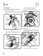
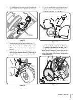
Страница 18: ...ing the three self tapping screws that secure it See Figure 7 2 Loosen the bolt shown in Figure 7 3 securing 3 the belt keeper bracket and remove the other bolt Push the belt keeper and bracket up off the engine pulley Auger Belt Replacement Remove the clip and flat washer from the ferrule in order 1 to disconnect the auger idler rod from the brake bracket assembly See Figure 7 4 Slip the auger be...

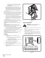
Страница 19: ...pulling up the handles a Block the impeller with a piece of wood to prevent 6 if from spinning and use a 1 2 wrench to remove the hex screw and washer from the center of the pulley on the auger housing See Figure 7 7 b Lift the brake bracket assembly out of the pulley groove and slide the pulley assembly off the posts of the auger pulley adapter to remove the old belt Refer to Figure 7 8 NOTE The ...

Страница 20: ...ven with the outside diameter of the pulley To adjust disconnect ferrule from brake bracket assembly 10 and thread ferrule in towards idler to increase tension on belt and out to decrease tension See Figure 7 4 NOTE The brake puck must always be firmly seated in the pulley groove when auger control is disengaged IMPORTANT Repeat the Auger Drive Control Test from the Assembly section before operati...

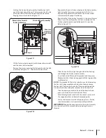
Страница 21: ...ough the right side of the housing and through the friction wheel assembly Insert the hex shaft through the sprocket and the spacer Make certain that the chain engages both the large and the small sprocket NOTE If the sprocket fell from the snowthrower while removing the hex shaft align sprocket on chain place the sprocket on the hex shaft Position the hex hub of the sprocket toward the friction w...

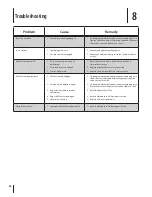
Страница 22: ...fer to Maintenance 1 Adjustments section Replace drive belt Refer to Service section 2 Replace friction wheel Refer to Service section 3 Unit fails to discharge snow Chute assembly clogged 1 Foreign object lodged in auger 2 Auger control cable in need of 3 adjustment Auger belt loose or damaged 4 Shear pin s sheared 5 Stop engine immediately and disconnect spark plug wire 1 Clean chute assembly an...

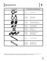
Страница 23: ...38 04155 Shear Pin 714 04040 Bow tie Cotter Pin 790 00091 Slide Shoe Deluxe Steel 731 06007 Slide Shoe Plastic 731 07032 Slide Shoe Polymer 731 2643 Chute Clean out Tool 790 00277 Shave Plate 30 inch 790 00196A Shave Plate 33 inch 790 00280 Shave Plate 45 inch NOTE Download a complete Parts Manual refer to customer support on page 2 Be sure to have your model number and serial number ready Refer t...

Страница 24: ...n Lifetime Warranty on Polymer Snow Discharge Chute If your product is a snow thrower equipped with a polymer snow discharge chute the Snow Chute and the Snow Chute fails breaks or malfunctions the manufacturer will repair or replace the Snow Chute at no cost as long as it is still owned by the original pur chaser or the original person for whom this product was purchased as a gift Control mechani...

Отзывы: