NOTE: For more details, refer to Drive Control Adjustment in the
Maintenance and Adjustment Section of this manual.
Auger Control Test
Check the adjustment of the auger control as follows:
When the auger control is released and in the disengaged
•
“up” position (see Figure 3-11), the cable should have very
little slack, but should NOT be tight.
WARNING:
Do not over-tighten the cable. Over-
tightening may prevent the auger from
disengaging and compromise the safety of the
snow thrower.
In a well-ventilated area, start the snow thrower engine as
•
instructed in the separate engine manual.
While standing in the operator’s position (behind the snow
•
thrower) engage the auger.
Allow the auger to remain engaged for approximately ten
•
seconds before releasing the auger control. Repeat this
several times.
With the auger control lever in the disengaged “up”
•
position, walk to the front of the machine.
Confirm that the auger has completely stopped rotating
•
and shows no signs of motion.
IMPORTANT: If the auger shows any signs of rotating,
immediately return to the operator’s position and shut off the
engine. Wait for all moving parts to stop before readjusting the
auger control cable.
To readjust the control cable, unhook the spring (found
•
on the end of the auger cable) from the auger actuator
bracket. See Figure 3-12.
Push the cable coupler through the end of the spring to
•
expose the lock nut. See Figure 3-13.
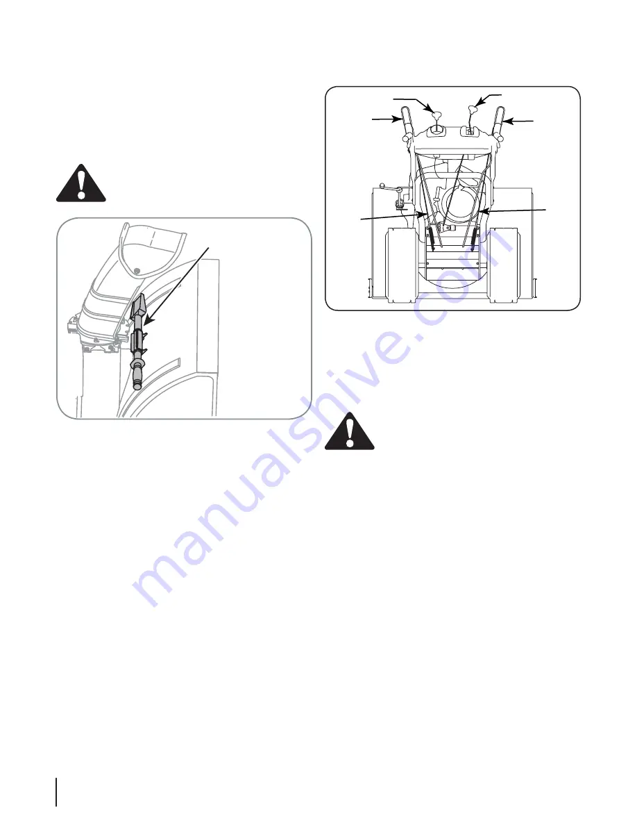
Clean-Out Tool
The clean-out tool is mounted to the rear of the auger housing
and is designed to clear a clogged chute. See Figure 3-10. Refer
to the Operation section for more detailed information regarding
the chute clean-out tool.
NOTE: This item is fastened with a cable tie to the rear of the
auger housing at the factory. Cut the cable tie before operating
the snow thrower.
WARNING:
Never use your hands to clean snow
and ice from the chute assembly or auger housing.
Final Adjustments
Make these final adjustments before operating your snow
thrower for the first time. Failure to follow these instructions may
cause damage to the snow thrower.
Wheel Drive Control & Shift Lever
Perform the following test to determine need for adjustment:
Move the shift lever into sixth (6) position. See Figure 4-1.
•
With the drive control released (see Figure 3-11), push the
•
snow thrower forward, then pull it back. The machine
should move freely.
Engage the drive control and attempt to move the machine
•
both forward and back, resistance should be felt.
Move the shift lever into the fast reverse (R2) position and
•
repeat the previous two steps.
If you experienced resistance rolling the unit, either when
repositioning the shift lever from 6 to R2 or when attempting
to move the machine with the drive control released, adjust the
drive control immediately. To adjust, proceed as follows:
Loosen the Nylock nut on the drive control cable and
•
unthread the cable one full turn. See Figure 3-13.
Recheck adjustment.
•
Fig. 3-10
Fig. 3-11
Clean-Out Tool
Drive
Control
Drive
Control
Cable
Auger
Control
Auger
Control
Cable
Shift Lever
Chute Tilt Control
10
S
ectioN
3— a
SSeMbly
& S
et
-u
p


