7.3.3 B24-SR
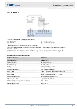
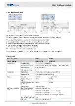
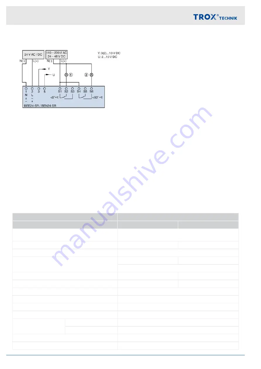
Fig. 23: Wiring example 24 V AC / DC, modulating
①
Indicator light for CLOSED position, to be provided
by others
②
Indicator light for OPEN position, to be provided by
others
Y
Working range (target value)
U
Position feedback (actual value)
Attention:
An input voltage of 0(2)...10 V DC at the operating range Y (terminal 3) is essential as the control input signal for
the actuator!
–
0(2) V DC = closed
–
10 V DC = opened
Terminal 1 is used as a common earth contact for the operating range Y as well as the position feedback U.
The current must be limited to max. 0.5 mA for measuring the position feedback (actual value)!
In addition, observe the following instructions
Chapter 7.2 ‘Wiring and connection to the central BMS’
Technical data of continuously controlled actuators
Order code detail
B24-SR
Actuator
BEN24-SR TR
BEE24-SR TR
Supply voltage
supply with safety transformer
AC 19.2...28.8 V, 50/60 Hz /
DC 21.6...28.8 V, 50/60 Hz
Power consumption – when running
3 W
3 W
Power consumption – when idle
0.3 W
Power consumption rating
6.5 VA
5.5 VA
8.2 A, Imax. (5 ms)
Torque
15 Nm
25 Nm
Run time
< 30 s (90°)
< 60 s (90°)
Work area Y
2...10 V DC
Input resistance
100 kΩ
Position feedback signal
2...10 V DC, max. 0.5 mA
Positional accuracy
±
5%
Limit switch
Type of contact
2 changeover contacts
Switch rating
1 mA...3 A (0.5 A inductive), AC 250 V
IEC protection class
III (SELV)
Protection level
IP 54
Electrical connection
Actuators > B24-SR
Smoke control damper EK-JS
42
Содержание EK-JS
Страница 53: ...Decommissioning removal and disposal Smoke control damper EK JS 53...
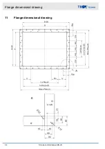
Страница 54: ...11 Flange dimensional drawing Flange dimensional drawing Smoke control damper EK JS 54...
Страница 57: ...Smoke control damper EK JS 57...
Страница 58: ...Smoke control damper EK JS 58...
Страница 59: ...Smoke control damper EK JS 59...

